
UPDATE: The RetroPie GPIO Adapter is replaced by the ControlBlock, which supports more controller types and provides even a power switch functionality. The ControlBlock is has its own page here.
 If you want to use your Raspberry Pi for gaming you certainly want to attach some sort of controller(s) to it. Since the Raspberry comes with two USB ports one way would be to simply attach any sort of USB gamepad or joystick via these ports to it. Besides the configuration this approach has the disadvantages that one or both USB ports become occupied and, what I think is even more disturbing, that an active USB hub might become necessary to provide enough energy to the controller(s). Also, if you want to get the real retro feeling you certainly want to use original controllers. The GPIO pins of the Raspberry allow the communication with all sorts of hardware and attaching, for example, SNES controllers can be done in quite a few steps. A user-space program that polls the controller(s) in the background was presented here. In the following I am presenting a dedicated GPIO adapter for the Raspberry Pi that allows an easy and safe connection of up to two NES or SNES controllers.
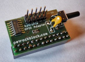
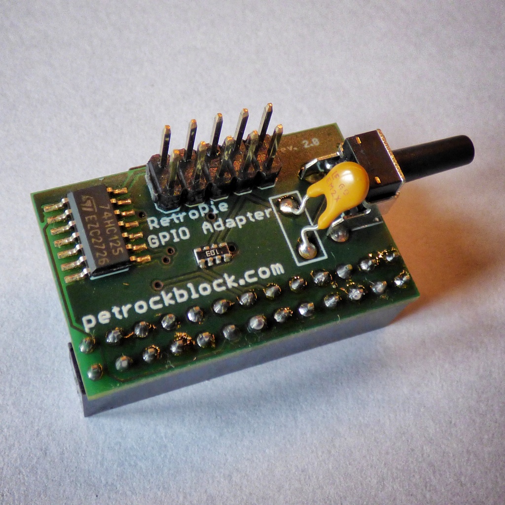
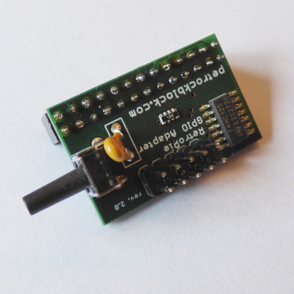
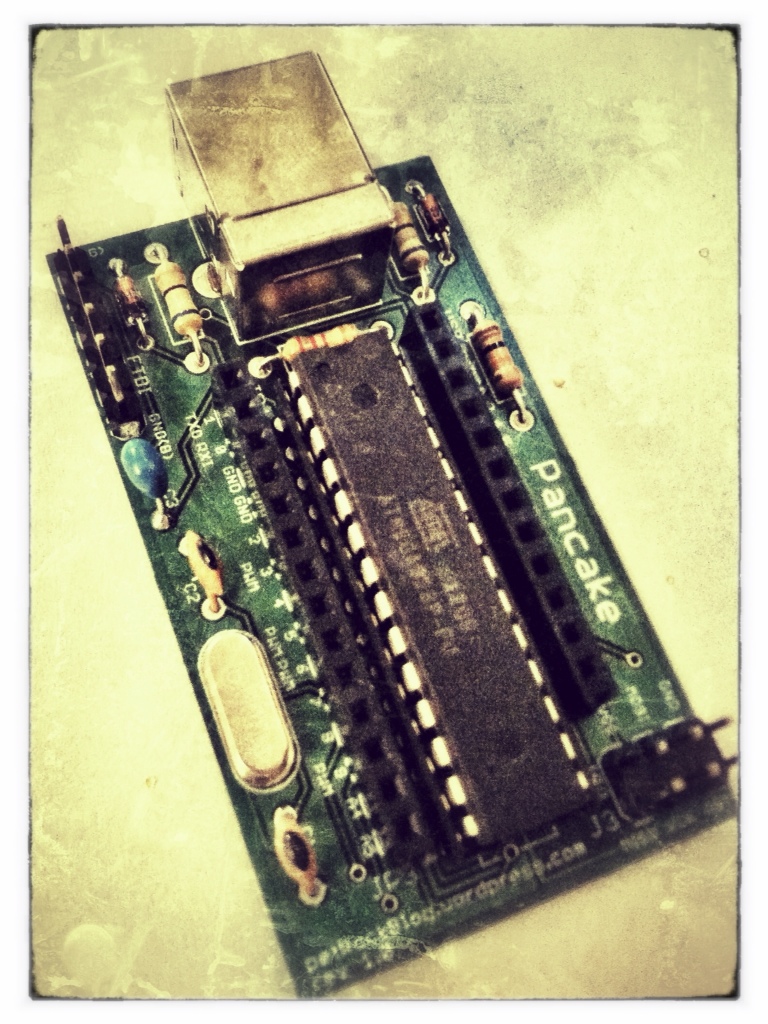
The RetroPie GPIO adapter
Based on the experiences with a previously presented adapter PCB I designed a new SNES adapter PCB specifically for the use with the Raspberry Pi.
Hardware
This GPIO adapter aims at
- an easy and practical installation
- as well as providing circuitry protection
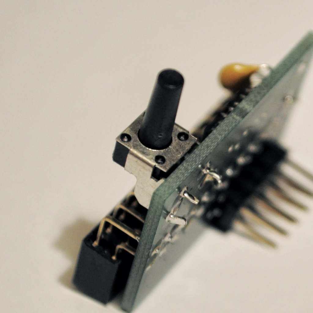
- and a button that can be used arbitrarily by software
Update 28.09.2014: Revision 2.0 of the RetroPie GPIO Adapter is released! The functionalities of revision 2.0 are exactly the same as the previous revision. However, the hardware design has changed due to the Raspberry Pi (TM) model B+ design. In contrast to revision 1.X, the new RetroPie GPIO Adapter revision is now mounted horizontally on the RPi. In the following descriptions of the adapter, photos of both revisions will be shown.
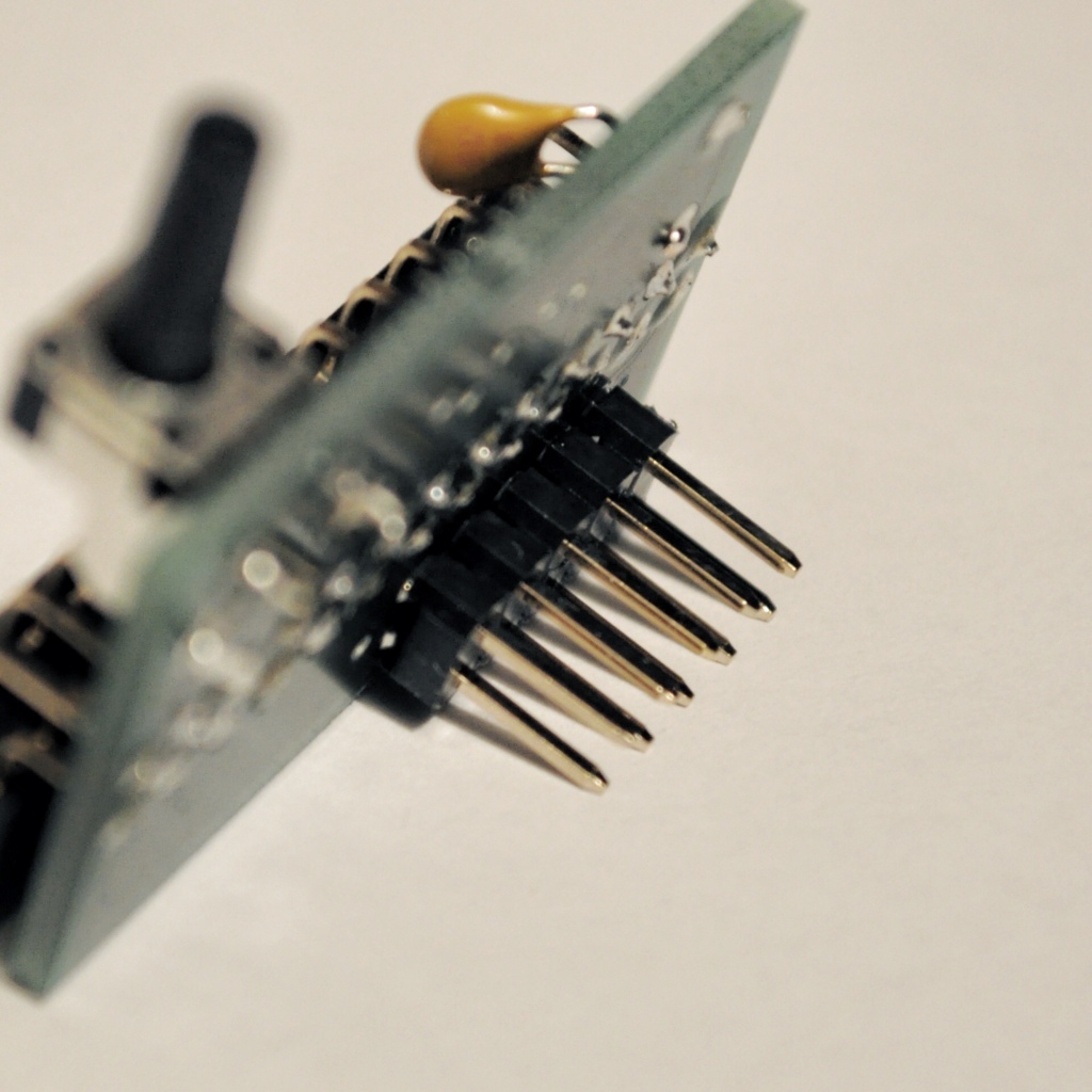
An easy and practical installation of the adapter board is achieved by using a 2×13 pins female header for a connection to the GPIO pins and 2×5 pins male header for the connection to, for example, (S)NES controller sockets. The only tinkering needed for a connection to (S)NES connectors is the soldering of the ribbon cable to the connectors. The size of the adapter PCB is only 0.91 in x 1.32 in (23 mm x 33.5 mm). This size does not increase the needed overall volume of the Pi much and allows the usage of most existing cases.
A word to SNES sockets: One way for obtaining these is to use the ones from SNES extension cables. Alternatively, a community member published 3D models of the connectors here.
For a practical application the adapter is provided with a circuitry protection as it was proposed in a thread of the official Raspberry Pi forum. To handle over currents a resettable fuse is put on the supply rail. Possible transients are taken care for by a buffer IC 74HC125. As stated by RPi wiki site about circuitry protection these ICs provide an in-line connection which is buffered via an internal transistor switch to isolate the input from the output.
Four GPIO pins, which would correspond to two data lines, the clock, and the latch in case of (S)NES controllers, are buffered by the adapter.
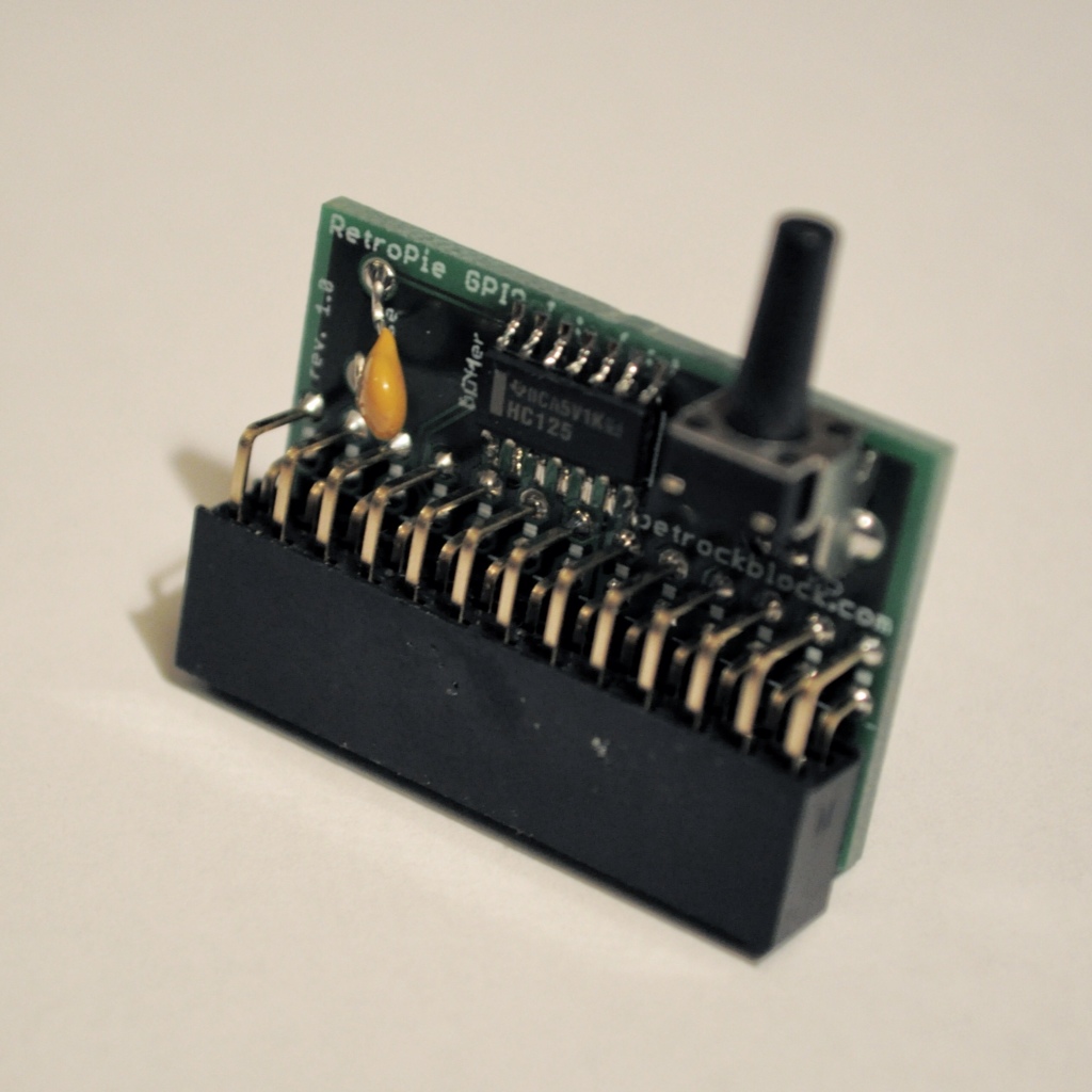
A momentary on push button is also part of the adapter board. The button is also connected to one of the GPIO pins and, thus, the status of the button can be polled with any suitable software. This allows, for example, to add a reset/back button that is needed with a keyboard-less setup and controllers with no redundant buttons like the SNES or NES controllers.
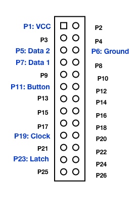
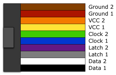
Pin Out
The exact pin out together with the according pins on the SNES connector are listed in the following and shown in the diagram (for revision 1.X of the Raspberry Board):
- VCC (3.3V): pin 1
- Ground: pin 6
- Clock: pin 19 (out)
- Button: pin 11 (in)
- Latch: pin 23 (out)
- Data 1: pin 7 (in)
- Data 2: pin 5 (in)
Connectors pin out for (S)NES connectors: The (S)NES connectors are soldered to a 10-wire ribbon cable that has a 2×5 pins female ribbon crimp connector at the other end. The pin out together with the according pins on the SNES connector are shown in the diagram:
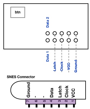
The pin out of the ribbon cable can be derived from the 2×5 pin header and is as following (shown from the top side):
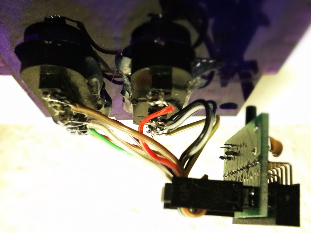
Here is an image of two SNES connectors soldered to the ten-wire ribbon cable and connected to the adapter board. Note that the 2×5 pin header has to point inwards the Raspberry Pi PCB:
For those of you that are interested in the components details, here are the manufacturer part numbers:
- Tri-state buffer: SGS-Thompson Microelectronics M74HC125M1R
- PTC resettable fuse: ESKA LP60-010
- Momentary switch: APEM PHAP3305D
Schematics and assembly Guide: You can find the schematics of the RetroPie GPIO Adapter revision 1.X and assembly guides here.
A comprehensive guide for getting started with the adapter can be found in this post.
Additional GPIOs on revision 1.X: It can also be seen from the schematics that revision 1.1 of the adapter breaks out four additional GPIO pins (GPIO pins 0, 14, 21, 22) together with ground and the 3.3V pin. This provides the possibility to attach additional hardware to the GPIO and use the RetroPie GPIO adapter at the same time. Note, however, that these additional pins do not provide any circuitry protection.
The dimensions of the adapter revision 1.X match the ones of the PetRockBlock PIE case. This means that both can be combined with each other to build a keyboardless gaming console with the RPi at its center. The RetroPie GPIO Adapter revision 2.X has a different hardware design is not compatible to the PetRockBlock PIE case.
Software
In order to use the RetroPie GPIO adapter a driver is needed that reads the states of the controllers and the button and maps these to the input system of the operating system. This can be done in kernel- or in user-space. The SNESDev software is an example of an user-space application that interfaces with the controllers and the button on the RetroPie GPIO Adapter. It is recommend to use SNESDev as driver for the adapter board.
Adding a jumper between pins 5 and 6 of P1 results in /boot/config.txt being ignored (except for avoid_safe_mode) and a default cmdline.txt is applied, followed by loading kernel_emergency.img. As stated in the official forum
if you connect external hardware to that pin, the worst that will happen is it falsely triggers safe mode.
To avoid this safe mode when the adapter is attached a setting has to be made in /boot/config.txt. This could be done, for example, by opening the config.txt with
sudo nano /boot/config.txt
adding
avoid_safe_mode=1
and saving the changes with “Ctrl-X”, which has to be confirmed with “Y”.
Demo video
A video of the adapter in action can be found in this post.
Installation and Troubleshooting
You can find a complete getting-started guide for the RetroPie GPIO Adapter on this page.
With the SNESDev driver enabled you can test for working connections between the game pads and the RPi with the jstest command (Ctrl+C exits the tool):
jstest /dev/input/js0
and
jstest /dev/input/js1
will test the first and the second game pad.
If you are using SNESDev for polling the game pads you need to use the option “poll game pads and button” in the menu of the RetroPie Script. If everything ism assembled and set up correctly button presses on the game pads will act as keyboard input and you will see according outputs on the console.
A long press (more than 1 second) on the button will lead to a key press of “r” which, again, can be checked on the console.
Conclusion & Getting it
The RetroPie GPIO adapter allows an easy and practical connection of NES and SNES controllers via the GPIO pins of the Raspberry Pi. The size of the adapter is kept as small as possible and should fit into most existing cases. It contains circuitry protection against over currents and transients. Furthermore, a momentary push button is installed on the adapter that can be used, for example, as a back or reset button. The pin out of the GPIO male header is matched to the already existing gamecon RPi GPIO driver, which can easily be installed and updated with the RetroPie Setup script.
If you are interested in an adapter please have a look here. The RetroPie GPIO Adapter kit also includes a ribbon cable (about 10 cm long) and a ribbon crimp connector.

The Atari CX40 Joystick is super easy — you should be able to just hook it up directly to the IO of the PI, with maybe some pull-up resistors, otherwise it should be the simplest controller in the world to interface with, since it’s just buttons going directly to wires (with a common on one side). — You should be able to hook them up the same way you hook up discreet arcade buttons (for like a PI based MAME cabinet) for example.
The NES and SNES ones shown here are also similarly easy, they’re basically one step up from that, in that they use shift registers to latch and then pass the data back in serial. — Otherwise, they’re basically the same thing.
Is there any way to get one of these?? Been OOS for over 4 months(that I’ve been checking). I bought a retrolink USB snes controller adapter, that the pi won’t recognize.
is there any way to get this to work with a PS1 controller? Just interested, as it will work with more emulators than a snes controller (couple more buttons :p)
Exuse me, can i use my pis plain old letter keyboard?
i need a respones TODAY OR TOMARROW
If i get the GPIO adapter, would I be able to connect an original NES Zapper, ie. to play Duck Hunt, Hogans Alley, etc. I know I can hook up the hardware, but does the SNESdev driver support it, and does it work as expected?
If i get the GPIO adapter, would I be able to connect an original NES Zapper, ie. to play Duck Hunt, Hogans Alley, etc. I know I can hook up the hardware, but does the SNESdev driver support it, and does it work as expected?
This thread might give you some ideas: https://www.petrockblock.com/forums/topic/please-help-brain-about-to-implode/
i got mine months back, don’t even know the exact date, could be summer 2014,but i just assembled it a month ago for my pi1 ;) i was lazy all the time and didn’t have my own soldering iron (which i have now ;) )
I was not aware of the fact that rev 1.x adapters were still sold. I will have a detailed look into this.
How do I attach the GPIO Rev 1.x to a Raspberry Pi 2 ? Mine doesn’t seem to work on it
Hi, do you provide the Eagle schematics / board layout files for the GPIO adapter somewhere? Thanks
You may also want to pin out 7 and 8 to be able to use one of these: https://www.pi-supply.com/
Hi Pierow, I found this when I was looking for the same thing… Have not yet tested it, but it should work. It’s all USB to “keyboard-mappings”. :)
https://icomp.de/shop-icomp/en/shop/product/keyrah-v2.html
Hello there.
I am experiencing strange behavior with two original snes pads. I didn’t use the adapter, but the pinouts described in the article. In the game both pads work as expected.
BUT when trying to configure the controller for emulationstation only one of the two pads is recognized on port one. If I interchange the pads so that pad 2 is connected to port one it is not recognized by emulationstation.
Has anyone an explanation for this behavior?
Is there a way to interface with an Atari joystick? Something like a CX40 or compatible? I’m most interested in emulating a C64 and would like to use my old controllers if possible.
Hello,
First, many thanks for the great job :)
I assembled my GPIO adapter and configured the drive of my 2 SNES pads and the button with SNESDev.
Everyting seems to work as expected. The button works perfectly, both of the pads work with jstest and in emulationstation as well.
My problem is when I launch any emulator, I get the messages saying “Joypad port #1/#2 SNES to gamepad device connected”, but in the games, none of my pads are working.
I tried to disable the joypad autoconfig and set a fixed configuration in the config of retroarch without any success.
I use also on my pi a Logitech rumblepad2 which works well (in both fixed/auto config).Is anyone has an idea about this?
Thanks in advance,
I think I was installing too much stuff maybe yeah. I’ll try just installing a fresh copy with the SD image and then just activate the SNESDev and that’s it. Thanks for the tip !
What steps did you make for the configuration of SNESDev? Did you install additional controller drivers, e.g. the gamecon one, (bluetooth) PS3, or Xbox 360? The Raspberry Pi is known to behave non-deterministic when certain USB devices are connected.
I can assure you that the delay does not come from SNESDev, which is the device driver for the RetroPie GPIO Adapter. To test your adapter setup, you could use a fresh SD-card installation and activate SNESDev from within the RetroPie-Setup Script. This step registers the SNES connectors as game pad devices and can be used, e.g., for configuring the input for EmulationStation.
HI, I’ve ordered, received, soldered and configured my PetRock Block GPIO adapter, I’m using it with 2 generic SNES controller socket that I’ve soldered with the adapter as well.
Everything “works” but it’s very sluggish, almost unusable! The ABXY + R/L + D-pad buttons work with 1/2 second latency, and the Start/Select buttons for some reason I have to hold the button nearly 1 second for it to be activated. I tried it with Super Mario World, and the pause screen wouldn’t come up when Start was pressed normally, I really had to hold the button. It’s very frustrating!
Now I’ve bought all that stuff because I was told that it was better than regular USB controller or adapter, almost cost me 30$ in total with shipping! I have a PS2 to USB adapter with which I used it with a Logitech Wireless Controller, It was working very well. But I needed a second controller and I had Original SNES controller laying around, so I figured I might put them to use. I really regret buying the Petrock Block GPIO adapter.
Up to now I’ve tried it with EmulationStation Ver. 1.9.1 & 1.10.1, I will try it with the new one but I doubt it will change anything regarding the slugginess.
Anyone has a solution ??
Thanks !
Great to hear! Will be ordering one of these very shortly :)
Hi Jacob, the RetroPie GPIO Adapter also has a pin out for the 5V input as well as for GND and 3.3V output. Thus, you could use a shutdown circuit like the Mausberry one with the GPIO adapter.
Hi there, great product! I was wondering whether it would be possible to use this GPIO Adapter alongside say a Mausberry shutdown circuit as I would rather the on/off switch soft shutdown the rPi. Thanks, Jacob
Ok, that’s great to know, so this is normal behaviour it would seem. My problem is that I can’t get js0 to respond. Are you using the gpio adapter or did you just wire your control ports directly to the gpio?
Also which version of the raspberry pi do you have?
SNESDev registers as two joysticks in Raspbian. Because of this you can use jstest to poll the two game pads and see the status of the buttons. Because they are handled as joysticks SNESDev will not lead to key presses when the joystick buttons are pressed. However, the button that is part of the RetroPie GPIO Adapter leads to a simulated key press by SNESDev. I hope this clears things up a little bit.
I just wanted to thank you for this post. You just saved my day. I was having similar issues where I could not get any of my controllers to respond. I was using the SNESDev driver, and was expecting a button press on the controller to type a number to the console. Using jstest (and realizing the js1 is player 1 and js0 is player 2…), it showed that the buttons were getting pressed. I will follow a similar approach to yours and just use those numbers in the retroarch.cfg file. Not sure why jstest picks up the button presses, but it doesn’t write anything to the console. I thought that SNESDev was basically a virtual keyboard…
Thanks a lot for that feedback! The next revision of the Adapter will have separate pin outs for GND and 5V!!
Hi! Thank you for your great effort with this excellent adapter, I’m currently slowly building me a Retro Arcade (will come back with pictures and links later)… However I do have a suggestion to improve the adapter a bit i think. I’m going to fit everything in a small a box as possible, so I’mm going to feed the power through the GPIO port (5v (pin 2) and gnd (pin 6)) instead of USB. I don’t want to use the micro USB port to power the PI because it adds to much to the total length. I will basically solder two extra pins on top of the GPIO connector on your adapter. My suggestion is that you just change the PCB so there are two extra holes to solder pins for a alternative power source to be plugged in to. :)
The gamecon driver and SNESDev must not run at the same time.
Maybe you get some other ideas at for a solution at https://www.petrockblock.com/forums/forum/retropie-project-forum/emulators/
Hmm, I did try installing the latest SNESDev but I’m getting a failure to compile error upon completion. It says see debug log for info but there’s nothing useful I can see there accept a line about ‘/home/pi/RetroPie/supplementary/SNESDev-Rpi/bin/SNESDev’ not existing. No idea why that would be a problem, creating that directory doesn’t seem to fix it.
There’s a couple of things I’m unclear on. Is jstest used for SNESDev or Gamecon? The description in the article above implies that it is for gamecon, which suggests that I do have gamecon enabled even though I never told it to install. However I lose the jstest function if I disable SNESDev, which would imply that they go together. Additionally, even though I managed to get one control pad working, pressing it’s buttons doesn’t result in keyboard strokes in the console, and unless I’m mistaken that should happen if I’m using snesdev. Lastly, I’m not sure why the controller with it’s data connection on pin 7 detects as js1, because I thought pin 7 was for js0 and pin 5 for js1.
Can you confirm for me the current pin configuration for SNESDev and gamecon? Are they the same? I have found some articles suggesting they are the same and some suggesting they are different.
Basically the way I ended up getting the control pad to work was by running Jstest, taking note of what numbers each button was associated with and then modifying the input lines in retroarch.cfg to match this. I dunno if any of that is informative.
I appreciate your attempts to help me.
You can install the gamecon driver with the RetroPie Setup Script. If you did not use the RetroPie Setup Script to explicitly enable the gamecon driver then you most probably do not have it installed.
You can try and install the latest version of SNESDev via the RetroPie Setup Script via the source-based installation. Make sure that you only select SNESDev there.
How do I ensure that the gamecon driver is not running? I never elected to install it in the setup, is it running by default?
Take care that SNESDev and the game con driver is not running at the same time, because both do interfere with each other.
Hi, I wonder if you can offer me any advice with the issue I’m having, or direct me to where I could find some help. I have put a raspberry pi into an old NES and I am having some trouble getting both controllers to work, here is where I’m at so far:
I have a 512MB revision B raspberry pi. I used the latest retropie img for my installation. Enabled SNESDev to poll just for the pads. Wired up the control ports to the GPIO as per instructions you’ve provided elsewhere, with data1 on pin 7 and data2 on pin 5. However only the player one controller seems to work. I can do a jstest for js1 and everything works fine, but I simply get no response on js0 (this is a little strange because I thought js0 was player1, but it appears to be the other way around).
Things I have eliminated as an issue:
It’s not the controller itself, they both work if I try them in the first control port.
I don’t think it’s my wiring, I tested it all with a multimeter and if I swap the data 1 and 2 wires then control port 2 works flawlessly instead (as js1), suggesting that all my voltage, clock, latch, ground and data wires are all fine.
It almost seems as if the pin itself (pin5) is not working properly, but I don’t know if that’s possible or how I would test it.
Please let me know if there is any other information I can provide to help shed light on this, or if I should be asking elsewhere. I am a real novice with this stuff, but I have managed to get everything working so far, I just can’t get player 2 controls to work, otherwise I am able to navigate the menu, and play nes games with the player 1 controller just fine.
One other thing, there appears to be some input lag, is this normal? I had originally tried to get the gamecon driver working instead because it should be faster, but no matter what I tried it kept giving me errors that my kernel needed to be updated or something like that.
Cheers,
Hugh
Thanks a lot it work ! BTW amazing work ! Greetings from Mexico
SNESDev simulates the press of the ESC key – so it is not a joystick button!
The setting in RetroArch that is responsible for exiting the emulators by a key is
input_exit_emulator = “escape”
This configuration comes per default with the RetroPie Setup Script.
If you want to use a gamepad button for exiting the emulators then you need to enable the “hotkey” functionality within retroarch.cfg.
hello
question, what is the button # for the reset/back button connected to pin 11 (in) and Ground: pin 6
I want to configure RetroPie/configs/snes/retroarch.cfg
lline
input_exit_emulator_btn = “bt#”
thanks!
Help Please, im still not able to use the back/reset button
i added
input_exit_emulator_btn = “9”
to RetroPieconfigssnesretroarch.cfg
but is not working :(
A longer ribbon cable should be fine!
If you have any other question I would point you to https://www.petrockblock.com/forums/topic/snes-gpio-setup-help/. Of course, you can also send me a mail!
Hi, I recently received the adapter board, thank you very much! I just have a quick question however, would it introduce any issues if I used a longer ribbon cable, crosstalk, signal degredation etc..?
The emulators need to be configured separately from Emulation Station, e.g., in /home/pi/RetroPIe/configs/all/retroarch.cfg.
Also what is odd is that the controllers and all the buttons are detected perfectly with EmulationStation, but not with RetroPie.
Thanks for the quick response!
I’ve only tried it with the NES emulator so far.
I’ve tried many different ROMs, all with the same issue.
I’m using NES controllers connected to the GPIO. Trying to keep the project as retro as possible.
Does this also happen with emulators other than NES?
Also, some ROMs have problems with two controllers (see, e.g., https://github.com/retropie/RetroPie-Setup/issues/158). Unfortunately, there is no overview about this topic so far.
Do you have NES or SNES controllers connected to the GPIO adapter? In its current version SNESDev follows the protocol for SNES controllers. SNES and NES controllers are very similar in their protocol so that SNESDev might also work with NES controllers out-of-the-box. However, I did not test this yet and it could be that I would have to update SNESDev for that (which would not be so much work).
Hello – I’m having a slight issue that has been driving me mad and was hoping someone here could kindly point me in the right direction.
I have RetroPie running on my RPi, the only emulator I have installed is NES. I have ROMs loaded and the function fine with the keyboard. I recently purchased the RetroPie GPIO Adapter, wired it up and attached it to my Pi. I enabled SNESDev with the SetupScript. I launch EmulationStation which prompts me to configure joysticks. Both controllers function perfectly and register. I then run the retroarch-joyconfig scrip and receive errors about pre-pressed buttons, however it allows me to map the ones I need for NES. I manually edit the cfg file to add joypad1 for player2. When I run a game all buttons on player2 function fine, and all buttons except the ‘B’ button on player one work fine. I first figured it was a bad controller, but I swapped it with a working one an the ‘B’ button fails.
Has anyone run into an issue like this before? Please let me know if you need any further information.
The button works as described at https://github.com/petrockblog/SNESDev-RPi#button-polling.
It is important that you have enabled SNESDev with controllers and button polling via the Setup Script. Currently, the behavior oh the button can only be modified by changing the sources of SNESDev and recompiling it.
I got my controllers working with SNESdev using your RetroPie image, but the button does not seem to do anything. Can you point me in the right direction for either configuring the button for exiting the emulator and shutdown or configuring a multi-input button sequence for the same purpose?
I did not expect it to work out-of-the box with a Multitap, to be honest. At least SNESDev would need to be modified or the wiring, if you use the gamecon driver.
I tried the multitap-support yesterday, it´s not working :(
thx for your response =) I think the best way to find out: i will triy it as soon as the adapter is connected to the snes-pins, maybe tomorrow.
I have not tried to attach a Multitap yet. I am not sure, but I think that the Multitap needs all pins of the SNES connectors. The RetroPie GPIO does not provide a corresponding pin for each of the connectors pins, but only uses “clock”, “latch”, “GND”, “VCC”, and “data” (see also RetroPie GPIO Adapter Schematics). However, the adapter provides additional break outs of GPIO pins, which could also be used. The software side (the gamecon driver and SNESDev) would probably also needed to be modified.
I will post some Pics on sunday =)
Just one Question: does the gpio-adapter support Multitap?
Thanks a lot! And thank you for your order, which directly supports this blog :-)
Your project sounds very interesting and I am sure that quite a few people would be interested in pictures in the forum.
Ich bin auch mal so frei und poste auf deutsch ;-)
Ich verfolge das Projekt hier schon einige Zeit, und habe jetzt für mein Pi den gpio adapter bestellt (danke für die nette Bestätigungsmail =) ).
Einsatzzweck: wird direkt an die Controlleranschlüsse eines alten, defekten SNES gelötet, welches als Case für das Pi fungieren wird (entsprechende Stromanschlüsse für USB & LED sind schon verlegt). Ein paar Bilder kann ich bei Interesse gern hochladen.
Lange Rede, kurzer Sinn: vielen Dank für all die Mühen, die du dir hier mit dem Blog etc. machst, es ist einfach sehr inspirierend!
Yes, it is possible. The GPIO adapter “just” provides protection circuitry against current and voltage transients. So you need to take care for that, if you directly connect the SNES controllers to the GPIO pins. The adapter also makes the connection with the SNES controllers easier by using a 2×5 pins connector as interface to the SNES connectors.
So am I able to connect 2 snes controllers directly to the GPIO pins? Such as hard wiring both controller’s clocks to GPIO pin18, and so on with the rest?
Thanks for sharing that info! I have added this post to the wiki at https://github.com/retropie/RetroPie-Setup/wiki/Setting-up-an-N64-controller.
i recently started messing with it again, and used an n64 controller instead. not only does it have more buttons, it also has less to connect, just + at pin 1 gnd at 6, and data at pin 7. as long as you put in
gamecon_gpio_rpi map=0,0,6,0
in /etc/modules
it starts right up on boot. you also need to run
cd ~/RetroPie/emulators/RetroArch/tools
./retroarch-joyconfig
and save the output to your retropie config file (this is a lot easier if you do it by ssh, with copy paste into vi/nano) to
~/RetroPie/configs/all/retroarch.cfg
i never did get an nes controller to work, and i tried several, including a NES Advantage. i know it was wired up right because the leds lit up
Besides testing the button circuitry with the testbutton program provided with SNESDev you would also need to ensure that the pins data1 and data2, clock, and latch are working fine. You can use a multimeter for that. Note that due to the tri-state buffer you need to consider polarity (see also the schematics of the GPIO adapter above).
danke für die schnelle Antwort. kann ich davon ausgehen, dass der gpio Adapter funktioniert durch die Tatsache, dass testButton einen Anschlag verzeichnet? dann werde ich mich auf die suche nach einem snes machen und meinen Controller kontrollieren vielleicht ist dieser beschädigt. Falls der Testbutton Anschlag kein Zeichen für einen funktionierenden Adapter ist gibt es eine Möglichkeit um nachzuvollziehen ob der Adapter funktioniert (mit einem Spannungsmesser o.Ä.)? außerdem werde ich noch einmal die Verbindung zwischen dem kabel und dem snes Adapter prüfen. Dort hatte ich Probleme, da das Plastik sehr schnell geschmolzen ist.
testbutton prüft tatsächlich “nur” den einen Knopf an dem GPIO-Adapter. Die Funktionsweise der angesteckten SNES-Controller kannst Du mit jstest /dev/input/js0 (bzw. js1) kontrollieren. Wenn alles richtig gelötet wurde, kann man mit jstest sämtliche Knopfdrücke nachvollziehen. Deiner Beschreibung nach Schätze ich, dass irgendwo noch ein Hardwareproblem vorliegt.
Ich bin mal so frei meine Frage auf Deutsch zu formulieren :)hallo ich habe folgendes Problem:
ich habe mir den Adapter zum selber basteln gekauft alles zusammengelötet und eigentlich keine Probleme gehabt. ich habe den Adapter an meinen pi angeschlossen und testbutten laufen lassen testbutton zeigt mir immer wenn ich auf den angelöteten Knopf drücke an Pressed aber nicht, wenn ich einen Knopf auf dem Pad drücke. Nun habe ich meinen SNES controller angeschlossen (auch beim Adapter keine Probleme gehabt alles sieht so aus wie auf den Bildern. Dann habe ich alles wie in der Anleitung installiert. Ich habe einmal den Einstellungsbildschirm für den Controller angezeigt bekommen leider hatte das drücken von tasten keinen einfluss und ich habe alles auf die Tastatur gelegt. Ich habe die emulationstation geschlossen. Dann habe ich probiert, ob jstest meinen Controller erkennt. Manchmal blinkt kurz on auf oder die Achsen zeigen komische werte an. Ich bin ratlos viellicht ist mir doch beim löten ein fataler Fehler unterlaufen… dann würde ich mir noch mal einen fertigen Adapter kaufen, wenn die wieder vorhanden sind. Aber vielleicht habe ich ja auch etwas vergessen ich hoffe du kannst mir helfen.
Yes, it is! The GPIO adapter introduces circuitry protection and, possibly, an easier way for attaching SNES connectors/pads.
I write about the connection of SNES controllers to the GPIO pins at https://www.petrockblock.com/2012/07/03/snesdev-rpi-a-snes-adapter-for-the-raspberry-pi/.
On the software side you could use SNESDev (https://github.com/petrockblog/SNESDev-RPi) to poll the game pads.
Is it possible to just direct wire the 2 SNES Connectors to the Raspberry, or is the Adapter needed? I am bored right now, and would like to play with SNES Controllers.
hey andy, im interested in getting the pre-assebled GPIO adapter, where can i get one?
All right, I finally put the few lines of manufacturer part numbers into the article!
Thanks for the reply Florian. I recompiled the source, and it seemed to work. Since then, I used the testButton program (sorry, didn’t see it before), and all is fine. Now I get a heap of warnings (cuts out of the game to command, and then back again) which says: RetroArch [WARN] :: [GL]: Stock GLSL shaders will be used.
But the GPIO works fine! thanks!
Manufacturer part numbers are usually consistent and can be cross referenced with any retailer.
I have to prepare the list. I could prepare a link list to the dealer I used here in Germany (which is not one of the big ones like Farnell or RS Components) or I could prepare a link list using a more internationally operating distributor. Do you have a preference here?
Did you install the gamecon driver and/or SNESDev?
Did you try to poll the button state via the testButton program in the supplementary folder of SNESDev?
Do you have the possibility to test the connection between the game pad and the RPi with a breadboard (without the GPIO adapter on between)?
This is a good project. I recently bought a GPIO adaptor (pre-assembled), and installed all the software from the RetroPie-Setup script. And for the life of me, I can’t seem to get anything working from the controller. I can’t even get the jstest to work.
I have a Rev 1 RPi, and have set the memory split to 128. What am I doing wrong? I have double and triple checked the pinouts, and all is as it ‘should’ be.
What am I missing?
Do you have a parts list of the board? Like What type of switch. Omron?
Adding such an image to the article might be a good idea to ease things up. Thanks for the hint :-)
That are great news!
The program “testButton” is also working for you and indicating button presses now?
I suggest adding a picture of the GPIO adapter attached to the board on this blog for dummies like myself :)
ok…I’m an idiot and shouldn’t be doing this at midnight….I had assumed the 2×5 headers faced outward on the RPi…..when I was testing I realized 3.3vdc is on the other side of the RPi….I flipped the board around with the 2×5 headers facing inward and all seems to be well with the button. I’m using USB controllers for now so I will not be abled to test the gamepad polling until a later time.
I was able to test continuity between vcc -> s1-2, s1-1 -> p1-11, p1-11 -> r7, GND -> r7, and GND -> p1-11 pulled down when button pressed
Yes, I have many electronic components available to me. Maybe you could describe the circuit? Also, yes I have a Rev 2 board.
Do you have a revision 2 RPi? Maybe testButton has a bug related to revision 2 boards … I should better check this.
I use an LED circuits to test the boards without any software involved. If you have the material you could do the same. Until now there were no hardware problems with the adapters after delivery so that I hope we can figure this out with software :-)
Thanks. I got it working on a breadboard..works great! I also ordered your GPIO adapter and just got it in the mail…unfortunately the button on the GPIO adapter isn’t doing anything….testButton isn’t seeing anything pressed. How can I troubleshoot your board?
If you’re using the gamecon driver I would suggest to ask this in the forum thread at http://www.raspberrypi.org/phpBB3/viewtopic.php?f=78&t=15787.
when i use retroarch joyconfig, it says
Found joypad driver: sdl
Configuring binds for player #1 on joypad #0.
A button (right)
but no buttons do anything
from the log
18.352978] input: NES pad as /devices/virtual/input/input0
[ 18.363678] NES pad data pin connected to GPIO1
[ 18.375374] input: NES pad as /devices/virtual/input/input1
[ 18.389085] NES pad data pin connected to GPIO4
[ 22.700835] mmc0: missed completion of cmd 18 DMA (512/512 [1]/[1]) – ignoring it
[ 22.711408] mmc0: DMA IRQ 6 ignored – results were reset
[ 28.982775] input: SNES-to-Keyboard Device as /devices/virtual/input/input2
gpio 1 is the pin number on the old revision, mine is a new revision board
i will flip contoller 1 to pin 4(physical 7) and 2 to pin 1 (pin3)(physical 5) confused yet?
The game pads do not produce any output on the console. When they are recognized by the jstest tool they will work with the emulators, if the configuration is correct. For RetroArch you can use the tool “retroarch-joyconfig” to obtain the button numbers for your game pads. With these numbers you can adapt the retroarch.cfg accordingly.
With the gamecon driver installed you would use SNESDev only for polling a button on P11. You can set up SNESDev via the RetroPie script (in the setup menu).
The pin numbers in the schematics are automatically created by EAGLE. These, however, do not correspond to the *physical* pins of the RPi. The button of the adapter uses the physical pin 11 of the GPIO pins of the RPi.
Hi, I’m trying to implement just the button, and it looks like in your schematics, the button goes to pin 16, but everyone here is saying pin 11.
http://petrockblog.files.wordpress.com/2012/11/retropiegpioadapter-schematics.pdf
I have a rev 2 Pi and am having no luck getting the controllers to work. the (regular nes) controllers show up as connected to GPIO3 and 4 (pins 5 and 7) clock is at 19, latch at 23, power and gnd at 1 and 6. Emulationstation is fully operational w/ keyboard. but the controllers show no signs of life. What I need to know is how to configure the SNESDev and gamecon drivers for nes controllers. I managed to edit the /etc/modules to make the controllers register as NES (with the right amount of buttons in the /dev/joy0 test) I modified the arch config and blanked out l,r,x, and y and renamed select and start to buttons 2 and 3. I have yet to have any button or axis map to a key, I get no response in the terminal. i did short out 11 and get it to reboot also. What do i need to do to diagnose the problem? does rev 2 need a different clock/latch?
I did everything laid out but still no luck. I went and tried to do the debug but since my button is only for escape and that doesn’t show up. I changed the key from KEY_ESC to KEY_R just for debugging with sudo SNESDev 2&. I noticed r really doesn’t show up with any consistency when the button is pressed. I did have a couple of times it showed up but that was it and in no way consistent. It shows up fine on the testButton script still though.
Sounds good, we are getting close!
Without further testing, I would modify the source of main.c of SNESDev like this:
case BTNSTATE_PRESS:if (buttonState==LOW ) {
btnLastTime=time(NULL);
btnState = BTNSTATE_RELEASE;
} else if (buttonState==HIGH && btnPressCtr==1 && difftime(time(NULL),btnLastTime)>1) {
/* send_key_event(uinh, KEY_R,1); */
}
break;
case BTNSTATE_RELEASE:
if (buttonState==LOW && difftime(time(NULL),btnLastTime)>1 ) {
if (btnPressCtr==1) {
// Sending ESC
send_key_event(uinh, KEY_ESC,1);
usleep(50000);
send_key_event(uinh, KEY_ESC,0);
} else if (btnPressCtr==3) {
// Sending ESC
send_key_event(uinh, KEY_ESC,1);
usleep(50000);
send_key_event(uinh, KEY_ESC,0);
} else if ( btnPressCtr==5 ) {
// shutting down
pollButton = 0;
pollPads = 0;
send_key_event(uinh, KEY_F4,1);
usleep(50000);
send_key_event(uinh, KEY_F4,0);
system("shutdown -t 3 -h now");
}
btnLastTime=time(NULL);
btnState = BTNSTATE_IDLE;
btnPressCtr = 0;
} else if (buttonState==HIGH ) {
btnLastTime=time(NULL);
btnState = BTNSTATE_PRESS;
btnPressCtr += 1;
}
break;
After compiling you have to makee sure that the just compiled version is used. Without calling the RetroPie script again, you can copy the new binary to
/usr/local/bin/and restart the service viasudo service SNESDev restart.For debugging purposes, you could also run SNESDev directly via
sudo SNESDev 2&and simulate, e.g., a press of the “x” button. You should see the “x” in the console. Do not forget to kill the SNESDev process afterwards viasudo killall SNESDev.Okay, the test button is finally running and it recognizes button presses. Button state: PRESSED when pushed and Button state: NOT PRESSED when not pushed. I can restart the SNESDev service so that is running. Still not getting the exit out of the emulator though with the a press (I edited the file so that 1 press should exit the emulator). I used the Retro Pie script to configure to poll for the button only. Any idea what is keeping it from working in game?
Yeah that’s fine with me.
Now that is great!
May I put this into a new “Showcase” category on the PetRockBlog site?
Ok, again “git pull” to update SNESDev and testButton. Then “make clean” and “make”.
You have to run testButton with “sudo ./testButton”.
After you have compiled SNESDev you have to enable SNESDev on boot with the RetroPie script in order to have it recognized as a service! The script takes care for copying the necessary files to the right locations. You can have a look the steps in detail at https://github.com/retropie/RetroPie-Setup/blob/master/retropie_setup.sh#L814.
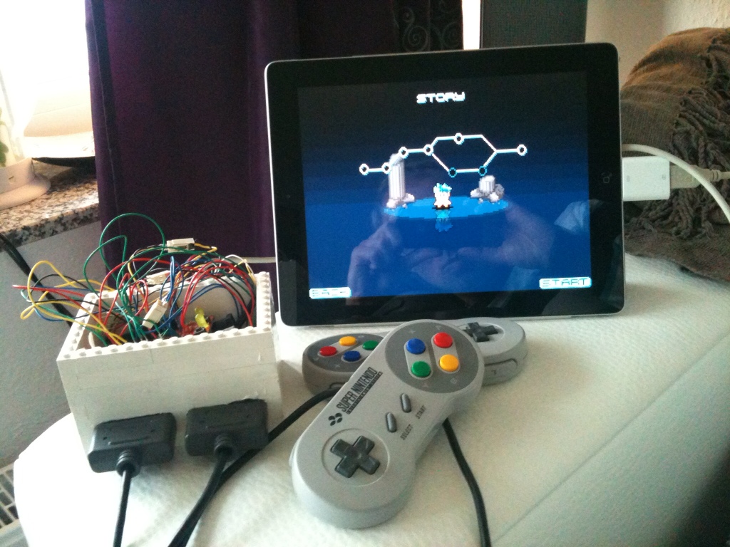
Here’s my SNES using the GPIO adapter. It’s still a work in progress but mostly functional.
http://www.reddit.com/r/raspberry_pi/comments/15axgn/raspberry_pi_super_nintendo_video_in_the_comments/
Ok, I’ll have a look at it tomorrow.
SNESDev was able to compile without any errors. Still was given the error about it not being a service when I tried to restart it (not sure if that matters, I just want to make sure I don’t leave anything out) Also, still not having any luck getting the testButton to run. Info is below. Thank you for continuing to help me with this.
pi@raspberrypi ~/RetroPie/supplementary/SNESDev-Rpi/supplementary/testButton $ make clean
rm *.o; rm testButton
rm: cannot remove `testButton’: No such file or directory
make: *** [clean] Error 1
pi@raspberrypi ~/RetroPie/supplementary/SNESDev-Rpi/supplementary/testButton $ make
gcc -c -Wall -O3 -Iinclude -lbcm2835 main.c -o main.o
main.c: In function ‘main’:
main.c:28:7: warning: implicit declaration of function ‘printf’ [-Wimplicit-function-declaration]
main.c:28:7: warning: incompatible implicit declaration of built-in function ‘printf’ [enabled by default]
main.c:30:7: warning: incompatible implicit declaration of built-in function ‘printf’ [enabled by default]
gcc -c -Wall -O3 -Iinclude -lbcm2835 cpuinfo.c -o cpuinfo.o
gcc main.o cpuinfo.o -lbcm2835 -o testButton
/usr/local/lib/libbcm2835.a(bcm2835.o): In function `bcm2835_delayMicroseconds’:
/home/pi/RetroPie/supplementary/bcm2835-1.14/src/bcm2835.c:350: undefined reference to `clock_gettime’
/home/pi/RetroPie/supplementary/bcm2835-1.14/src/bcm2835.c:360: undefined reference to `clock_gettime’
collect2: ld returned 1 exit status
make: *** [testButton] Error 1
pi@raspberrypi ~/RetroPie/supplementary/SNESDev-Rpi/supplementary/testButton $ sudo ./testButton
sudo: ./testButton: command not found
There was a dependency missing in the Makefile of SNESDev. Furthermore, I have uploaded a wrong version of main.c for testButton. I am sorry for that!
I am not at home right now, so I did a “quick fix” via the Github interface. Both issues should be fixed now and I hope that I did not miss anything.
Does it work now?
Okay, that got rid of a lot of the pin errors, still had errors when trying to make SNESDev.
pi@raspberrypi ~/RetroPie/supplementary/SNESDev-Rpi $ git pull
Already up-to-date.
pi@raspberrypi ~/RetroPie/supplementary/SNESDev-Rpi $ make clean
rm obj/*.o; rm bin/SNESDev
rm: cannot remove `bin/SNESDev’: No such file or directory
make: *** [clean] Error 1
pi@raspberrypi ~/RetroPie/supplementary/SNESDev-Rpi $ make
gcc -c -Wall -O3 -Iinclude -lbcm2835 -lrt src/main.c -o obj/main.o
gcc -c -Wall -O3 -Iinclude -lbcm2835 -lrt src/SNESpad.c -o obj/SNESpad.o
gcc obj/main.o obj/SNESpad.o obj/cpuinfo.o -lbcm2835 -lrt -o bin/SNESDev
gcc: error: obj/cpuinfo.o: No such file or directory
make: *** [SNESDev] Error 1
In addition, it seems right now SNES isn’t even recognized as a servie
pi@raspberrypi ~/RetroPie/supplementary/SNESDev-Rpi $ sudo service SNESDev restart
SNESDev: unrecognized service
I’m sure that is causing me to still get the same error when trying to run the testButton
pi@raspberrypi ~/RetroPie/supplementary/SNESDev-Rpi/supplementary/testButton $ make clean
rm *.o; rm testButton
rm: cannot remove `*.o’: No such file or directory
rm: cannot remove `testButton’: No such file or directory
make: *** [clean] Error 1
pi@raspberrypi ~/RetroPie/supplementary/SNESDev-Rpi/supplementary/testButton $ make
gcc -c -Wall -O3 -Iinclude -lbcm2835 main.c -o main.o
main.c: In function ‘main’:
main.c:20:15: error: ‘RPI_GPIO_V2_P1_11’ undeclared (first use in this function)
main.c:20:15: note: each undeclared identifier is reported only once for each function it appears in
main.c:22:31: error: ‘BCM2835_GPIO_FSEL_INP’ undeclared (first use in this function)
main.c:26:6: warning: implicit declaration of function ‘bcm2835_gpio_read’ [-Wimplicit-function-declaration]
main.c:28:7: warning: implicit declaration of function ‘printf’ [-Wimplicit-function-declaration]
main.c:28:7: warning: incompatible implicit declaration of built-in function ‘printf’ [enabled by default]
main.c:30:7: warning: incompatible implicit declaration of built-in function ‘printf’ [enabled by default]
make: *** [main.o] Error 1
pi@raspberrypi ~/RetroPie/supplementary/SNESDev-Rpi/supplementary/testButton $ sudo ./testButton
sudo: ./testButton: command not found
Here is something else that may or may not be related in the debug file:
RetroArch files:
-rwxr-xr-x 1 root staff 1.3M Dec 1 17:34 /usr/local/bin/retroarch
-rwxr-xr-x 1 root staff 1.9K Dec 1 17:34 /usr/local/bin/retroarch-zip
/home/pi/RetroPie/configs/all/retroarch.cfg does NOT exist.
It starts with the configs folder not existing, but that may be a non-related issue, I don’t have any issues getting my usb controllers to work with the the file in /etc/retroarch.cfg
You also have to update the BCM library via the setup script. With the updated library the errors should be gone.
Okay, I tried to update SNESDev, but it wouldn’t update and said to check the debug log. Which only has this:
SNESDev:
/home/pi/RetroPie/supplementary/SNESDev-Rpi/bin/SNESDev does NOT exist.
I saw someone had the same issue earlier and followed what you put with pulling it and compiling. Here are the results:
pi@raspberrypi ~/RetroPie/supplementary/SNESDev-Rpi $ git pull
Already up-to-date.
pi@raspberrypi ~/RetroPie/supplementary/SNESDev-Rpi $ make clean
rm obj/*.o; rm bin/SNESDev
rm: cannot remove `obj/*.o’: No such file or directory
rm: cannot remove `bin/SNESDev’: No such file or directory
make: *** [clean] Error 1
pi@raspberrypi ~/RetroPie/supplementary/SNESDev-Rpi $ make
gcc -c -Wall -O3 -Iinclude -lbcm2835 -lrt src/main.c -o obj/main.o
src/main.c: In function ‘main’:
src/main.c:216:15: error: ‘RPI_V2_GPIO_P1_11’ undeclared (first use in this function)
src/main.c:216:15: note: each undeclared identifier is reported only once for each function it appears in
src/main.c:271:17: error: ‘RPI_V2_GPIO_P1_19’ undeclared (first use in this function)
src/main.c:272:17: error: ‘RPI_V2_GPIO_P1_23’ undeclared (first use in this function)
src/main.c:273:17: error: ‘RPI_V2_GPIO_P1_07’ undeclared (first use in this function)
src/main.c:274:17: error: ‘RPI_V2_GPIO_P1_05’ undeclared (first use in this function)
make: *** [obj/main.o] Error 1
Wasn’t sure if the error could be ignored, tried to copy the file
pi@raspberrypi ~/RetroPie/supplementary/SNESDev-Rpi $ sudo cp ./bin/SNESDev /usr/local/bin/
cp: cannot stat `./bin/SNESDev’: No such file or directory
So that didn’t work, your test button file was there but when I tried to compile and run it I got this:
pi@raspberrypi ~/RetroPie/supplementary/SNESDev-Rpi/supplementary/testButton $ make
gcc -c -Wall -O3 -Iinclude -lbcm2835 main.c -o main.o
main.c: In function ‘main’:
main.c:20:15: error: ‘RPI_GPIO_V2_P1_11’ undeclared (first use in this function)
main.c:20:15: note: each undeclared identifier is reported only once for each function it appears in
main.c:22:31: error: ‘BCM2835_GPIO_FSEL_INP’ undeclared (first use in this function)
main.c:26:6: warning: implicit declaration of function ‘bcm2835_gpio_read’ [-Wimplicit-function-declaration]
main.c:28:7: warning: implicit declaration of function ‘printf’ [-Wimplicit-function-declaration]
main.c:28:7: warning: incompatible implicit declaration of built-in function ‘printf’ [enabled by default]
main.c:30:7: warning: incompatible implicit declaration of built-in function ‘printf’ [enabled by default]
make: *** [main.o] Error 1
pi@raspberrypi ~/RetroPie/supplementary/SNESDev-Rpi/supplementary/testButton $ sudo ./testButton
sudo: ./testButton: command not found
Hopefully something in that will help you pinpoint what is going on with my board. Thank you very much for taking time to try and help me fix this. I appreciate it.
I have just updated the source trees of SNESDev and RetroPie-Setup. Please update your RetroPie-Setup version by going into that directory and calling “git pull”. Then start the script and select the source-based installation. Here, you install only the BCM library and SNESDev then.
When the installation is finished, go to the directory “~/RetroPie/supplementary/SNESDev/supplementary/testButton/”. It is a small C program which print the status of pin P1-11 to the console. To compile the program call “make”. Run it with “sudo ./testButton”. You can cancel the program with “Ctrl-C”. Are your button presses recognized by this program?
If your wiring is all good, it sounds like your connected to the correct GPIO pin- I’d check for updates on the script (git pull) and uninstall/re-install the SNES DEV components and see if that work.
I probably did a poor job of explaining it, but it is wired to be a pull down switch (the bottom picture). And with everything looking fine using the DMM, I’m guessing it has to be something on the software side. Which is where I really wonder what went wrong because it seems to me like the script would take away most of my ability to screw something up. But alas, I seem to have found a way, lol.
Sounds like you are having an issue like I did. Your switch sounds to be wired in as a pull up. It needs to be wired as a pull down. Pull down is what I needed to get it to work. If you look at this link- http://elinux.org/File:EGHS-PullUpDownSwitch.jpg – the top, I believe is how your currently wired, but you need to wire like the bottom. Try it out and let me know.
I went ahead and checked out the setup with my multimeter. There were not shorts between VCC and ground, the switch is open unless the button is pushed, so that isn’t broken. From the outside, the circuitry is doing what it should, having 0 V outside pin 1_11 until the button is pushed and then it goes high to 3.3V. My setup is installed in the pi user folders. I know one of your articles stated that the uinput could only be used as root? So does my retro arch and everything have to be installed under the root user for this to work? If this is not the case, what would you need from me to try and determine what isn’t right on the software portion of it? Thanks for helping me out with this.
Your setup sounds fine and should be the same as the one of the adapter.
If you have it available I would recommend to test the circuitry with a multimeter and, in the best case, completely independent from the RPi with a separate power supply.
Check for short circuit between GNC and VCC. Also check for the correct VCC pin (3.3V, and not 5V).
Hello, I am trying to implement a push button using your idea to try and replace the escape key so I don’t need a keyboard for the setup. I am having issues getting it to work though and I was hoping you could help me. VCC (3.3 volt pin) is connected to the open switch, which then goes to one leg of a 1k resistor. This leg is also connected to pin 1_11, the same pin you would use with your adaptor. The other leg is connected to ground. Nothing is soldered, it’s all done using test clips until I know it works. I have installed SNES using the RetroPie script and set it up to poll for just the button since I am using usb controllers. Let me know where I need to look to try and get this working. Thank you.
turns out I either soldered it wrong, or it doesn’t work with that LED parallel to the controllers. I will make some changes later tonight and try again.
I found out something “useful”. When using the original controller board for the pal snes, the LED lights up. This will save me a lot of time wiring the LED to work on my build, but I hope the controllers get enough power. Ah well, I’ll see once the retropie installer finally is finished.
I will need to find out where to get the other parts I will need, and unsolder and extend a couple of things for better accessability (Like I want to wire up your the button on the PCB to the reset button, move the SD card slot, extend the USB ports, HDMI port, composite, everything really. Which means I’ll have to learn how to solder. This will take a while.
That sounds great! You can send me pictures of your project for a future showroom at the blog site!
I’ve just ordered the card. I’m planning on building my pi onto a snes, so unfortionately I’ll have to wait for my special screwdrivers to arrive so I can open the snes without damaging it before I can test.
Not that I know.
I could upload the schematics for the device that I use for testing the assembled adapters. Basically, it provides a visual indication for correctly working adapter by testing each line of the tri-state buffer as well as the button.
If I’ve got a short between VCC and GND, what’s the next culprit to look at? Has any one compiled a how to on what to test?
Dennis I think I may know what your problem is because I did the same thing. Prevously you listed the steps you took and you said you installed the SNESDev (controllers and pad) plus the gamecon driver. I took the same route and my controllers were super buggy. What you need to do is change the polling for SNESDev to “button only” then install the gamecon stuff. Basically you have SNESDev and gamecon both trying to control your gamepads.
I should add that I am new to all this and might be completely wrong. That said I now have my Rpi working perfectly with two SNES controllers. Hope that helps
Hi Dave, great to hear the the GPIO adapter is working for you!
For now you would have to modify the source code of SNESDev and re-compile it. Essentially, you would “just” have to move lines 163-165 (https://github.com/petrockblog/SNESDev-RPi/blob/master/src/main.c#L163) to line 160 (https://github.com/petrockblog/SNESDev-RPi/blob/master/src/main.c#L160) in main.c.
I hope this helps!?
I’m using your GPIO adapter and everything is working great. I’ve only got one question. Is there a way to edit what the button on the adapter does. I would like to have it quit a game after just one press instead of three. Thanks!
I don’t know exactly what happened, but it now works somehow. Not as good as I hoped, but it’s OK. Mario Kart works smooth only if I overclock to 1 Ghz, but I don’t want to use this setting the whole time. At 900 Mhz Mario Kart is still a bit slow (so I guess Mode 7 emulation is the cause), I tried Super Mario World + Street Fighter IV and I can play them at acceptable speed..
Things I did to get it working:
Tweaked retroarch video settings
Rebuilt SNES core/Retroarch from source via your script
ALSA is still not working for me btw, but I guess this is a common R-Pi issue.
Thanks a lot for your help. :) Now I need to find a cheap SNES and NES case to build my R-Pis into.
Just noticed a ton of error messages in the background when using alsa:
RetroArch [WARN] :: [ALSA]: poll() was signaled, but EAGAIN returned from write.
Your ALSA driver might be subtly broken.
It repeats over and over and may well be the cause for it being so slow for me.
Setting the driver to alsa had a very negative effect, it is even slower. It was set to sdl initially.
Disabling the rewind functionality brought a little performance boost, but not enough.
Great to hear that we also solved the SNESDev issue!
If it is not due to an “external” program I am pretty sure that you can tweak a lot with the settings in /etc/retroarch.cfg.
First of all disable the rewind functionality and also the audio_driver setting. Change the audio driver to alsa in a next step. Does this have any effect?
Cannot reply to your last related post.
That did the trick, it works now. :)
This is my ps aux output while running Super Mario Kart, omitting all 0.0 %CPU entries:
USER PID %CPU %MEM VSZ RSS TTY STAT START TIME COMMAND
root 1 0.7 0.2 2136 732 ? Ss 16:37 0:01 init [2]
root 4 0.1 0.0 0 0 ? S 16:37 0:00 [kworker/0:0]
root 12 0.2 0.0 0 0 ? S 16:37 0:00 [khubd]
root 27 1.3 0.0 0 0 ? S< 16:37 0:03 [VCHIQ-0]
root 28 0.3 0.0 0 0 ? S< 16:37 0:00 [VCHIQr-0]
root 33 4.0 0.0 0 0 ? S 16:37 0:09 [mmcqd/0]
root 138 0.2 0.5 2884 1296 ? Ss 16:37 0:00 udevd –daemon
root 1620 0.1 0.0 0 0 ? S 16:37 0:00 [RTKTHREAD]
root 1640 0.2 0.0 0 0 ? S 16:37 0:00 [kworker/0:2]
root 2279 0.4 1.3 10548 3316 ? Ss 16:38 0:00 sshd: pi [priv]
root 2299 0.1 1.4 26512 3708 ? Sl 16:38 0:00 /usr/sbin/console-kit-daemon –no-daemon
root 2366 0.1 1.1 23300 2928 ? Sl 16:38 0:00 /usr/lib/policykit-1/polkitd –no-debug
pi 2376 0.3 0.9 6128 2480 tty1 S+ 16:38 0:00 -bash
pi 2384 4.0 2.5 64272 6588 tty1 Sl+ 16:38 0:06 ./emulationstation
pi 2394 87.3 9.3 93712 23828 tty1 Rl+ 16:39 1:52 retroarch -L /home/pi/RetroPie/emulatorcores/pocketsnes-libretro
pi 2406 0.7 0.6 10548 1732 ? S 16:39 0:00 sshd: pi@pts/0
pi 2407 1.0 1.3 6784 3352 pts/0 Ss 16:39 0:01 -bash
pulseaudio was listed, but only with 0.0%, I can only see retroarch consuming a lot of CPU power. Did you tweak anything in the retroarch configuratoin?
Btw, if I get this thing running I will buy at least one more of your adapters in the future. I want to have a dedicated machine in a SNES case for SNES games only and one in a NES case for NES games only. Who knows, later maybe the same for Genesis…
I understand that my speed issue has nothing to do with your adapter, so it's OK if you can't give support. I watched your video of Super Mario Kart on youtube and it runs so much faster than mine…
That sounds reasonable ;-)
you should really make a wiki page from this issue ;)
What I did was to ssh into the RPi while running an emulator. With this I found that pulseaudio was using a lot of resources in my case. Maybe you find something similar with this approach.
This should be independent of the RPi board revision. Just to test it and to be sure that you are using the just-compiled version of SNESDev, you can start SNESDev from command line via
~/RetroPie/supplementary/SNESDev-Rpi/bin/SNESDev 2&Ups, I just found another typo: It must be /usr/local/bin/!
Restart the service via
sudo service SNESDev restartafter copying SNESDev to the correct location and things should (finally) work.And I simply copied and pasted the commands without thinking.
I redid that step and can now see that /usr/bin/SNESDev has a new time stamp, still the same behaviour. :(
I have a v2 board if that makes a difference?
As for speed, did you tweak anything? I have disabled “boot into desktop”, overclock settings as stated above and memory split 50/50.
I am sorry!
There was a typo in my last comment. It should read
sudo cp ./bin/SNESDev/usr/bin//usr/local/bin/Notice the slash at the end of command! If you leave this out it will copy SNESDev to a file “bin” within the folder /usr.
Output via HDMI is quite fast for me.
Hi,
here is the complete output:
pi@raspberrypi ~ $ cd ~/RetroPie/supplementary/SNESDev-Rpi/
pi@raspberrypi ~/RetroPie/supplementary/SNESDev-Rpi $ git pull
Already up-to-date.
pi@raspberrypi ~/RetroPie/supplementary/SNESDev-Rpi $ make clean
rm obj/*.o; rm bin/SNESDev
rm: Entfernen von âobj/*.oâ nicht möglich: Datei oder Verzeichnis nicht gefunden
rm: Entfernen von âbin/SNESDevâ nicht möglich: Datei oder Verzeichnis nicht gefunden
make: *** [clean] Fehler 1
pi@raspberrypi ~/RetroPie/supplementary/SNESDev-Rpi $ make
gcc -c -Wall -O3 -Iinclude -lbcm2835 src/main.c -o obj/main.o
gcc -c -Wall -O3 -Iinclude -lbcm2835 src/SNESpad.c -o obj/SNESpad.o
gcc obj/main.o obj/SNESpad.o -lbcm2835 -o bin/SNESDev
pi@raspberrypi ~/RetroPie/supplementary/SNESDev-Rpi $ sudo cp ./bin/SNESDev /usr/bin
pi@raspberrypi ~/RetroPie/supplementary/SNESDev-Rpi $ sudo service SNESDev restart
[ ok ] Restarting SNESDev GPIO Adapter daemon: SNESDev.
After that I held down the button for about 5-8 seconds, released it and…
Broadcast message from root@raspberrypi (Sun Nov 25 15:09:47 2012):
The system is going down for system halt NOW!
Even after a reboot -> same behaviour. Can it be that there is another copy of SNESDev somewhere because I tried the binary installation at one point?
And another thing, unrelated to your adapter, I have overclocked the pi via raspi-config like this:
“High”; 950 MHz ARM, 450 MHz core, 450 MHz SDRAM, 6 overvolt
Still Super Mario World + Super Mario Kart (only 2 games I have tested) are very slow. Is it because I output via HDMI?
Ok, let’s try it manually. First of all make sure that you have the latest sources:
cd ~/RetroPie/supplementary/SNESDev-Rpi/
git pull
Then, compile it:
make clean
make
The, copy SNESDev to the bin directory:
sudo cp ./bin/SNESDev /usr/bin/
Restart the SNESDev service via
sudo service SNESDev restart
Does it work?
Please forget about my joytest-problem and let’s not talk about it anymore. :P (It is working now and was of course my fault, I have connected Data 2 when I thought I had connected Data 1, so joytest /dev/input/js1 works now as it should).
On to the next:
pi@raspberrypi ~/RetroPie/supplementary/SNESDev-Rpi/bin $ ls -altr
insgesamt 8
drwxr-xr-x 8 pi pi 4096 Nov 24 17:16 ..
drwxr-xr-x 2 pi pi 4096 Nov 24 19:33 .
pi@raspberrypi ~/RetroPie/supplementary/SNESDev-Rpi/bin $
Am I missing something?
I see SNESDev writing logs, so yes, it must be there, but where?
(When I had no success to get the Source based installation running I tried the binary based installation and later the source based again…)
Thanks for your help.
/home/pi/RetroPie/supplementary/SNESDev-Rpi/bin/SNESDev should be the binary, and /home/pi/RetroPie/supplementary/SNESDev-Rpi/bin/ the containing folder.
Since you said that pressing the button leads to a shutdown of the system SNESDev must be there.
Btw, /home/pi/RetroPie/supplementary/SNESDev-Rpi/bin/SNESDev is empty… But that is a totally different problem I think.
Ah, I see. The pre-assembled ones were tested before shipping.
Small success:
Now jstest behaves differently, all buttons ‘flicker’ from ‘on’ to ‘off’ like mad, only when I press a button they stay ‘on’. Any idea what might be the problem? ‘Unclean’ soldering?
I should have stated that I have bought a pre assembled one. I only soldered the wire from the SNES Connector to your adapter.
I will now try to reinstall the latest SNESDev with ‘make clean’ && ‘make’ as you have suggested above.
I now have tested the ribbon crimp connector and I can see that the current should be able to flow between the crimp connector and the 5 pins from the SNES adapter.
I will check the schematics again, maybe I didn’t check careful enough.
Yes, it should say “on”, when the buttons are pressed. Two thoughts here:
1) It sounds as if (at least) your button is assembled and (hardware-wise) working correctly. However, it sounds as if you are not using the latest version of SNESDev. In a previous version a shutdown command was initiated when pressing the button for more than 3 seconds. This has changed with the more recent version of SNESDev.
2) Did you solder the tri-state buffer with the correct orientation on the adapter board? As stated in the assembly guide: “Pin 1 must be directed towards the fuse holes.”
Thanks for that. In parallel I was checking my soldering and that seems to be OK. What I cannot check with my multimeter is if the ribbon crimp connector is connected correctly (which could be a problem, like I said this is not my everyday business). But I can track that the current is flowing from the SNES adapter through the crimp connector.
Then I set SNESDev to only poll the button and rebootet. After that I tried to read the input with jstest, but again without success.
This is the output of jstest:
Driver version is 2.1.0.
Joystick (SNES pad) has 2 axes (X, Y)
and 8 buttons (BtnX, BtnY, BtnTL, BtnTR, BtnTR2, BtnSelect, BtnThumbL, BtnThumbR).
Testing … (interrupt to exit)
Axes: 0: 0 1: 0 Buttons: 0:on 1:on 2:on 3:on 4:on 5:on 6:on 7:on
Shouldn’t the buttons be ‘off’ without button press and ‘on’, when I press a button?
And I noticed something odd: When I press and hold the button for a couple of seconds nothing happens. Once I release it, the system shuts down. I though I have to push and release the button 5 times for the system to shutdown?
Sorry for keeping you busy. :-/
To check this in more detail you can change the directory to /home/pi/RetroPie/supplementary/SNESDev-Rpi/bin/SNESDev. Then you clean up the installation with “make clean” and compile SNESDev again with “make”. If anything wants wrong during that you will see it in this way. BTW: these are the steps that are done by the RetroPie script as well.
Ok, thanks for the detailed description!
I added a section ” Installation and Troubleshooting” above. This should help you!
Some additional data:
kern.log:
Nov 25 00:16:57 raspberrypi kernel: [ 16.877736] input: SNES pad as /devices/virtual/input/input2
Nov 25 00:16:57 raspberrypi kernel: [ 16.903560] SNES pad data pin connected to GPIO4
Nov 25 00:16:57 raspberrypi kernel: [ 16.933187] input: SNES pad as /devices/virtual/input/input3
Nov 25 00:16:57 raspberrypi kernel: [ 16.957803] SNES pad data pin connected to GPIO3
Nov 25 00:16:57 raspberrypi kernel: [ 87.465027] bcm2835-cpufreq: switching to governor ondemand
Nov 25 00:16:57 raspberrypi kernel: [ 87.465058] bcm2835-cpufreq: switching to governor ondemand
Nov 25 00:16:57 raspberrypi kernel: [ 88.992474] input: SNES-to-Keyboard Device as /devices/virtual/input/input4
Nov 25 00:16:59 raspberrypi kernel: [ 90.823551] Adding 102396k swap on /var/swap. Priority:-1 extents:1 across:102396k SS
So should it be working?
Think I should get a multimeter to check my soldering…
By the way, when I do the source based installation there’s also an error saying that it could not compile the SNESDev drivers and tells me to check the debug.log. But the debug.log only reads:
SNESDev:
/home/pi/RetroPie/supplementary/SNESDev-Rpi/bin/SNESDev does NOT exist.
I cannot find anything else about SNESDev there.
Hi, it’s me again… and I hope that my question isn’t again answered anywhere on this blog… :-/
Anyhow, I have done the following steps:
1. Started RetroPie-Setup
2. Option 2 Source Based Install
3. Options 1-11 enabled / 12-24 disabled / 25 enabled / 26 – 29 disabled / 30-34 enabled (I enabled everything except the emulators, I only chose the SNES emulator as I only want to emulate that)
4. Reboot after installatoin (just to be sure…)
5. Entered RetroPie-Setup again
6. Option 3 Setup
7. Start SNESDev on Boot -> Option 2 -> Polling pads and button
8. Install/Update multi/console gamepad driver for GPIO
9. Enable gamecon_gpio_rpi with SNES-pad config
10. Reboot
But: SNES Controller is not working… I am pretty sure it is because of my soldering, it is my first try in 12 years to solder a wire again, but yet I want to make sure it is not because of the steps above. Is there any way for me to test if my soldering is OK on the console?
Thanks
Dennis
If you use the button in combination with, e.g., RetroArch and SNESDev, a three-state automaton is implemented:
– press and hold: send “r” key (for rewind function of RetroArch)
– press and release three times: send “ESC”
– press and release five times: shutdown
This allows a keyboard less setup. I plan to post a demo video for these functions soon.
Maybe you have to update your RetroPie script. Just cd to the RetroPie-Setup directory and run “git pull”. You also need to have the latest SNESDev version. You can install it (together with the BCM library) via the source-based setup.
The latest version of the RetroPie Setup Script allows you to start SNESDev with different arguments (1, 2, or 3). I also just updated the README.md of SNESDev in the repository and updated information about the button usage.
I am curious and clueless at the same time: what is this button used for anyway?
Thanks for the Florian!
I enabled SNESDev in the retro-pie setup script but I do not see where I can configure the SNESDev to poll only the button. Could you provide more details as to where this is?
Thanks!
Hi! Yes – the button is wired to GPIO 17 (P1-11). As far as I know tetrarch-joyconfig looks for /dev/input/jsX devices (joysticks,gamepads, etc.) and is not any help here. Also, the gamecon driver is intended to poll Nintendo controllers that are wired to the GPIOs according to the pin out described above. Thus, it is not used if you are using USB drivers and you can disable it (remove or comment it in /etc/modules).
One way of polling the button on pin P1-11 is to use SNESDev, which can also be installed with the RetroPie Script. Select source-based installation and deselect everything except the BCM library and SNESDev. Afterwards, you can enable SNESDev in the setup menu. From that menu you can also configure SNESDev to poll only the button.
I hope that helps!?
Hello! I am interested in how you wired and configured your “momentary push button”. You mentioned that the “button is also connected to one of the GPIO pins and, thus, the status of the button can be polled with any suitable software”. But what GPIO pin is this? Is it GPIO 17 or P1-11 on the RPi? What other configuration / software changes were needed to enable this?
I have your retropie script installed with NES emulator working fine with the gamecon drivers installed, with the controller configuration of two NES to USB adapters working in retroarch. I have a momentary switch wired with a pull down resistor to the GPIO 17 (P1-11) and I am not getting the ./retroarch-joyconfig to recognize the button nor is emulation station recognizing the escape key when input_exit_emulator_btn = “btn#” is added to /etc/retroarch.cfg. I am not sure what button to replace “btn#” with or if I have the full configuation setup to sense this button.
Any help would be appreciated!
Hi Jeremiah, thanks for your interest! No worries – asking these kinds of questions is one way of learning.
You have a point that the 2×5 pins header only breaks out the pins needed for polling two controllers. With a little tinkering the other pins could be accessed by desoldering the desired pins on the PCB-side of the 2×13 pins header first, and then solder whatever you like to these pins. In this way you would at least have a possibility to access the other pins (without circuitry protection though).
personally, I have not practical experience with LCDs connected to the RPi, but I would try and go for an I2C adapter for the LCDs that are also sold by Adafruit. Synchronizing the displayed game on the LCD with the game that you are currently running on the RPi might be another problem that I would like to have (theoretically) solved before starting to design the hardware for it.
Hope that helps?
I am incredibly interested in trying this out, but I did have a concern. Firstly, I am fairly new to electronics and am probably missing something so feel free to call me stupid. I wanted to set up a RetroPie box with my raspberry pi, but in addition, I would like to display the system being emulated as well as the game being played with http://adafruit.com/products/399. My concern is that, your adapter takes up all of the GPIO pins, but doesn’t use them all. Is there a way the extra GPIO pins or am I just being ridiculous?
Thanks, I’ll wait for schematics, and still waiting for my controllers to arrive, then I will analyze what has to be done to connect them. Will definitely share my findings.
Hi, thanks for your interest!
Good idea – I will provide the schematics this evening.
Following SPI, two PSX controllers would need GND, 3.3V, MISO (in), MOSI (out), CLOCK (out), SS1 (out), and SS2 (out) – or do I miss something here?
Hi, could you provide a schematics of your new board? I would like to adopt it to psx controller.
Thanks
Florian… your work is amazing.
MACH WEITER SO! :)