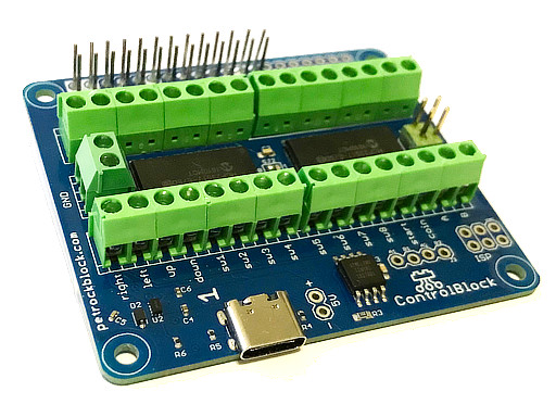
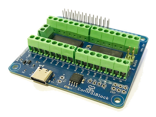
The ControlBlock
Elevate your Raspberry Pi® projects with the ControlBlock, a versatile extension board designed to enhance both safety and functionality. This innovative tool is specifically engineered to address two critical needs in Raspberry Pi® applications:
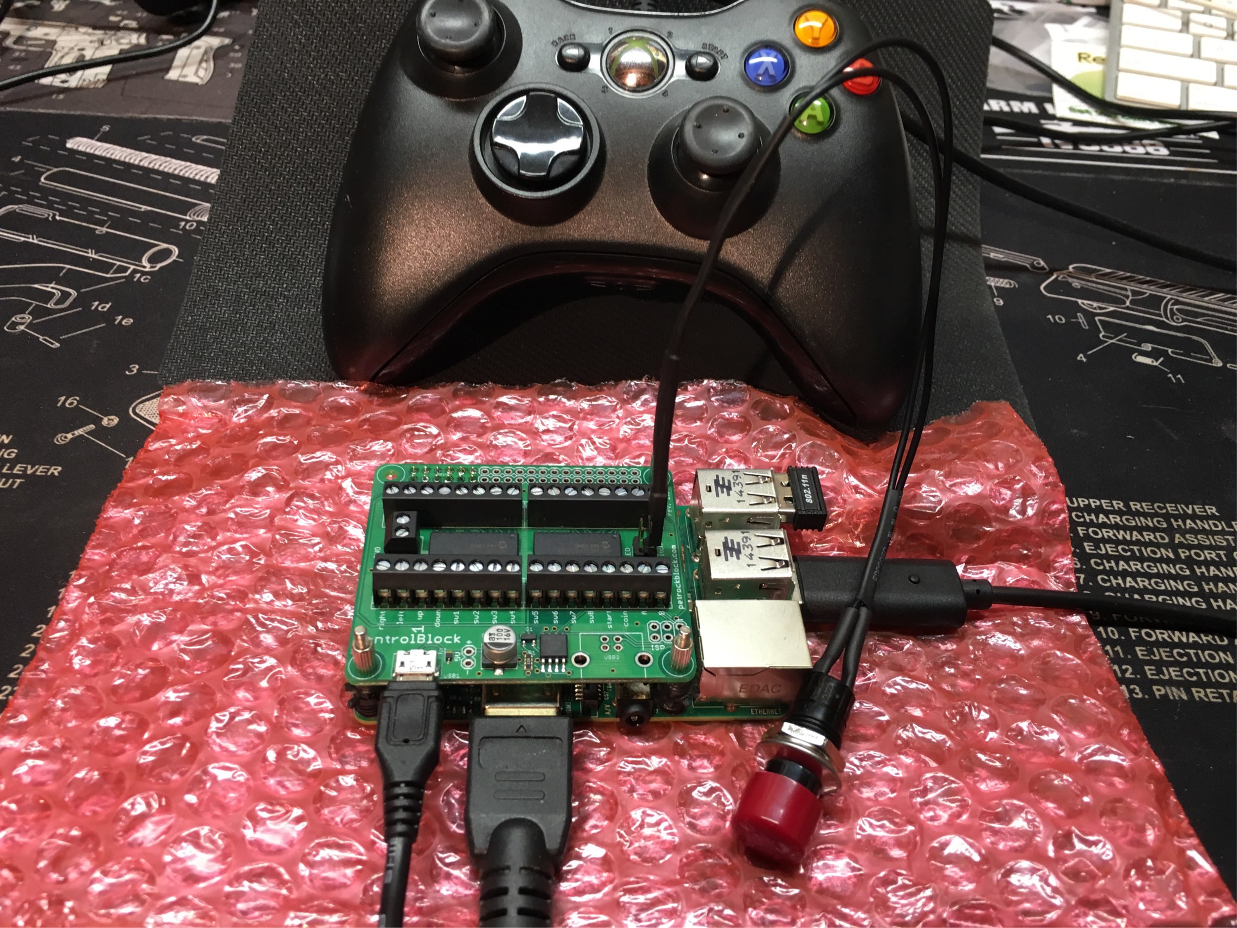
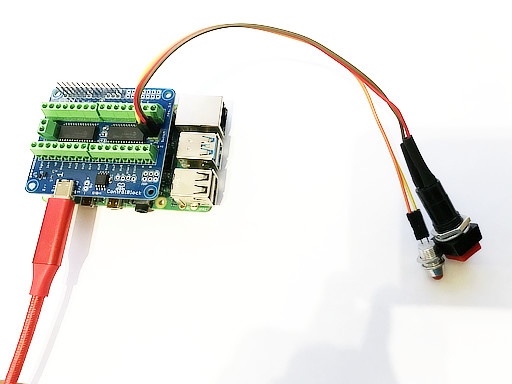
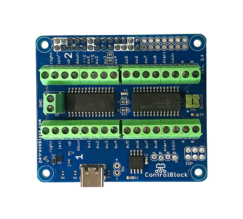
- Safe Power Button: The ControlBlock features a secure power button that allows for a safe shutdown of the Raspberry Pi®, ensuring no data loss occurs during the process. This feature is crucial for maintaining the integrity of your projects and protecting your data.
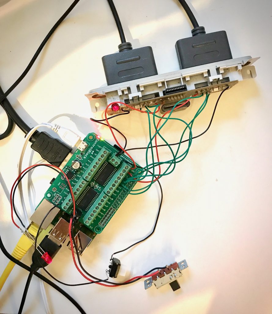
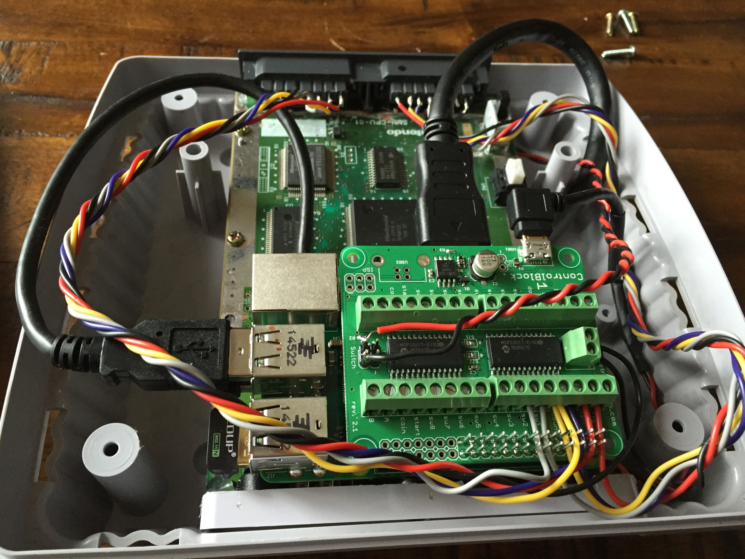
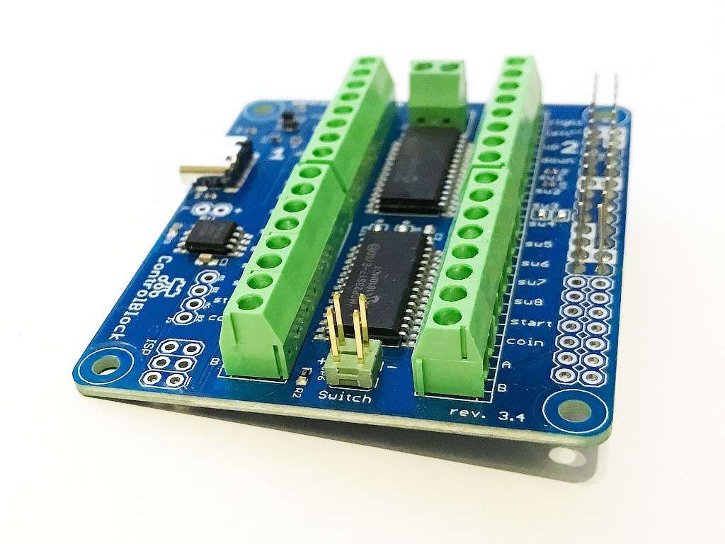
- Game Controller Interface: Alongside the safe power button, the ControlBlock offers a robust interface for connecting traditional game controllers. This functionality opens up a wide range of possibilities for arcade machines, game consoles, and any project that requires precise control inputs.
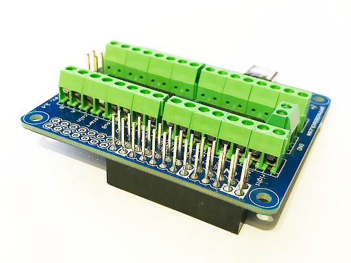
- I/O Expansion: The ControlBlock also includes terminal blocks for I/O expansion, providing additional connectivity options for your Raspberry Pi® projects. Whether you’re working on a DIY robotics project, a home automation system, or a custom gaming setup, the ControlBlock offers the flexibility you need to expand your Raspberry Pi®’s capabilities.
The ControlBlock is not just an extension board; it’s a toolkit for enhancing your Raspberry Pi® experience, offering a blend of safety, functionality, and expansion possibilities. Whether you’re a hobbyist, a professional developer, or an educator, the ControlBlock is the perfect companion for your Raspberry Pi® projects.