UPDATE: For connecting original controllers from game consoles or arcade machines, there is now the ControlBlock. It supported various controller types and provides even a power switch functionality. The ControlBlock is has its own page here.

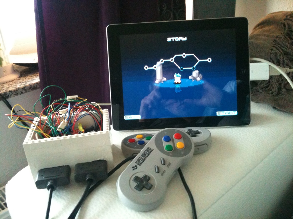
In a previous post, I described my idea of a universal console with the Raspberry Pi. I presented, what I called, the SNESDev-RPi, which is an SNES-controller interface for the Raspberry Pi. A core element of this interface is a SNES-adapter PCB that I recently designed and that does nothing more than providing all needed connections between the GPIO pins and two SNES connectors. In this post I describe the details for assembling the SNES-adapter that I showed in the previous post. Furthermore, I show how a single SNES socket can be directly connected to the GPIO pins of the Raspberry Pi.
This post is organized in two sections: The first section describes the details for assembling the SNES adapter with the PCB. The second section describes, how a single SNES socket can directly be connected to the Raspberry Pi.
Before I begin with the descriptions I want to say that both described approaches need soldering and work with heat and electricity. This means that you should know what you are doing when following these instructions!
Assembling the SNES adapter with the PCB
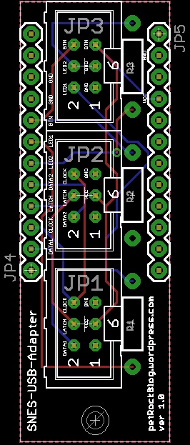
In this section I describe how to connect two SNES connectors to the SNES-adapter PCB that I recently designed. The PCB replaces some wires and makes it easily possible to attach two SNES connectors to the Raspberry Pi. If you are interested, here is an illustration of the board layout (click on it to enlarge):
For the assembly we need the following components:
-
- 1x SNES-adapter PCB
- Ribbon cable – 26 wire
- Ribbon Cable – 6 wire (from which we only use five wires)
- 1x Ribbon Crimp Connector, 2×13 pins
- 2x SNES connectors (I got these from two extension cables for SNES controllers)
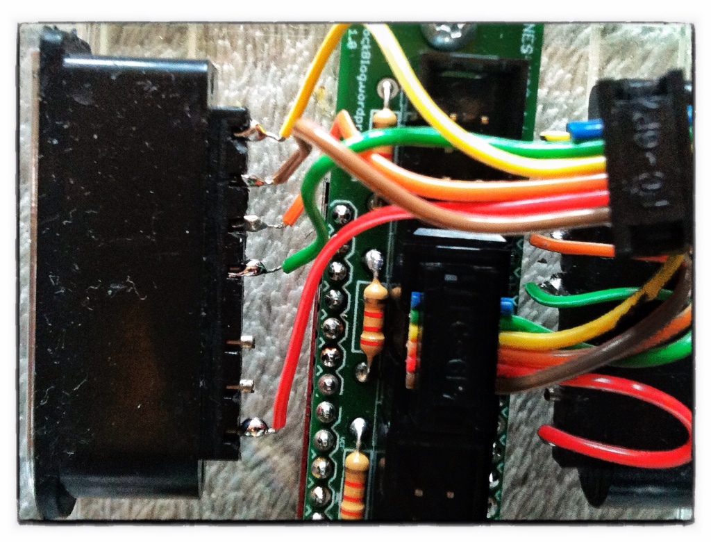
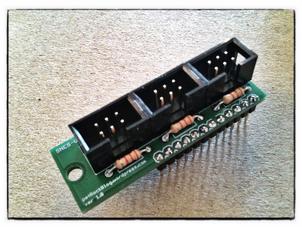
As you might have noticed I left out the shrouded pin headers used for the prototype as shown in the previous post. I realized that these take quite a lot of space. To allow for putting the whole adapter into a nice small case I decided to discard them here. The assembly consists mainly of dismantling the wires and soldering them to the pins and pads.
Here is a diagram that illustrates all needed connections between the connectors and the PCB (tap to show it in large). To be on the safe side, use pin 1, which provides 3.3V! According to other sources the polling of the SNES controller should also work with 3.3V.

The red lines illustrate the connections between the GPIO connector and the PCB. Here I chose those GPIO pins that are used in the SNESDev-RPi implementation. The connections between the SNES connectors and the PCB are indicated by pairs of numbers or capital letters and are shown in purple.
For the sake of completeness also the pin out for two optional LEDs and a button is shown. A button can be attached between the “b”s. An LED can be attached (watch the polarization!) between “n” and “GND” or “m” and “GND”, respectively. As already mentioned, the LEDs and the button are not used here. But if you want to use them, you also have to connect the LED and BTN pins on the left of the PCB to the GPIO connector. Also, you need to solder three resistors on the boad to make the circuits work. I used 2.2k Ohm 1/4W resistors, but similar ones would also do here.
Connecting a single SNES socket to the Raspberry Pi
In this section I describe how to attach a single SNES connector to the Raspberry Pi. We need the following parts for this:
- 1x Ribbon Crimp Connector, 2×13 pins
- 1x SNES connectors
The following illustrations shows the connections between the SNES connector and the 2×13 crimp connector. To be on the safe side, use pin 1, which provides 3.3V! According to other sources the polling of the SNES controller should also work with 3.3V.

The wiring between the crimp connector and the single SNES connector is equal to the one of the second SNES controller when using the SNES-adapter board. Notice that the button mapping within the source code of SNESDev has to be adapted to your needs in this case! Alternatively, you can connect the data pin of the connector with P22. If you do so, no changes to the source code of SNESDev should be needed.
Conclusions
I hope you find these descriptions helpful. Please tell me, If anything is still unclear so that I can add the missing information. If you have any ideas for improvements for the SNES-adapter PCB it would be great to share them here. While I wrote this post, for example, I got the idea that it might be easier to have a 2×13 connector directly attached to the SNES-adapter board. Also, some over-voltage protection would be reasonable for a future revision of the board.
If there are enough people interested in the SNES-adapter board, I already thought about designing another revised version of it …
What do you think?
I installed per instructions,one snes controller and the system (E.S.)sees the controller but buttons and pad do not react..same with if I run jstest it shows the controller but no inputs…..any suggestions?
Would it be possible to just wire up buttons to be a controller…. possibly two?
I would like to use the original controller board from the SNES(to keep the case looking as stock as possible. with this controller board, what would the differences in hookup be? not finding setup guides that use the original snes parts, only NES.
If EmulationStation is responding to controller inputs the wiring and driver setup are perfectly ok!
Currently, you need to configure your controllers for the emulators separately from Emulation Station. Please have a look into the forum for further instructions … this is one of the main open issues currently.
Looks like Matt’s comment from 2 years ago partially held the answer for me! My modprobe statement was incorrect, and should be modprobe gamecon_gpio_rpi map=0,0,2,0,0,0
Now I am closer. The gamepad is recognized and I can set up the button mapping in the “configure input” part of emulationstation. I can navigate the emulation selection and pick games with the NES controller! But once I select the game, the controller is not responsive, but my usb-attached keyboard is. Am I missing a configuration step. My sense is the wiring and the other setup are OK now…
Is there a simple sanity check that can be run from the command line that troubleshoots the connectivity of the controller hooked up directly to the GPIO as you describe above. I’ve put it together and taken it apart so many times that I’ve lost count. modprobe gamecon_gpio_rpi map=2,0,0,0 seems to work fine — and after it runs, emulationstation tells me that a controller is detected (though it says this even with no wires attached to the GPIO). However, when I go to set up my controller within emulationstation (with wires attached!), it doesn’t seem to recognize that I am pressing any buttons!
i have no preference on which driver to use. im just looking for how to configure it. Right now im wired for 1,5,6,7,23,19 the modprobe configuration is confusing the hell out of me. Best moderator ever BTW :P
If you want to use the gamecon driver you should use the 1,5,6,7,23,19 configuration. I admit that this could have been written a bit clearer.
I’ve see different pin connections. one set says use pins 1,6,15,16,18,22 for 3v3,ground,data1,latch,clock and data2 and another says use pins 1,5,6,7,23,19 for 3v3,data2,ground,data1,latch,clock and 2nd is the command string for modprobe and testing via joystick. the instructions and examples are a little confusing . im guessing map=0,0,2,2,0,0 (0,0 for disabled because its a new board and the instructions say to disable 1 and 2, 2,2 because its two nes controllers and 0,0 because theirs nothing connected.
my wiring color scheme blue=pwr green=grnd black=data1 purple=latch grey=clk white=data2
im confused about the configuration with modprobe mapping. 1st i see different pin connections. one set says use pins 1,6,15,16,18,22 for 3v3,ground,data1,latch,clock and data2 and another says use pins 1,5,6,7,23,19 for 3v3,data2,ground,data1,latch,clock and 2nd is the command string for modprobe and testing via joystick. the instructions and examples are a little confusing . im guessing map=0,0,2,2,0,0 (0,0 for disabled because its a new board and the instructions say to disable 1 and 2, 2,2 because its two nes controllers and 0,0 because theirs nothing connected.
my wiring color scheme blue=pwr green=grnd black=data1 purple=latch grey=clk white=data2
Yeah! I can read the schematic lol. Thank you for the quick reply BTW. im almost done with the soldering and my new Rpi will be here today.( i have a model B rev1 and want the new one)
Yes, that is correct.
great stuff. im building my own nes setup and have been looking for a while for the pinouts to the rpi. im going directly to the gpio from the back side of the ports. i wanted to ask if i understand correctly. both controllers share power, ground, clock and latch and only have data separately?
Hi Dave,
you can choose any free pin. In case of the RetroPi GPIO adapter, I chose pin 11 (see https://www.petrockblock.com/2012/10/21/the-retropie-gpio-adapter/). Just make sure that the program for polling the button state uses the same pin :-)
Hi.
when you connect the Button or LED to the board, you say that they then need to be connected to the GPIO connecter. Where on the GPIO do they need to be connected to?
Thanks, this is a great guide!
David
Thanks for the reply. I installed everything per your script and wired the controllers up. Configured them using your retropie_setup.sh. They work fine in the games but not at the menu. Is there an additional step/setting change I need to do to be able to use them?
In combination with the gamecon driver, SNESDev and Emulation Station it is possible to control the RPi as gaming platform with game pads only.
Is the controller supposed to operate the menu?
Do you see the output of pad 1 or 2 (according to the SNESDev source code)?
To check this, controller 1 should control the cursor in the terminal, controller 2 leads to the keys “a s d w” when pressing the D-pad.
Try to run a ROM without retroarch first.
I just found a post about a project that uses SNESDev at http://www.raspberrypi.org/phpBB3/viewtopic.php?f=35&t=15766. Maybe you can get a hint there as well!?
Hello Again,
I am using one controller and cannot get the SNES to see my controller even though the terminal can see it and when I press buttons on the controller it types letters in terminal but still nothing in the emulationstation. Can you help me?
Reblogged this on Gigable – Tech Blog.
Yes, you are right! I tried to point to this in the SNESDev post: “The SNES-adapter board really does nothing but to provide a clean wiring for the connectors.” Hence, you can replace it!
Looking at the PCB: Voltage, Ground, Latch, and Clock should be common between both controllers. The difference should be pin 1 (data 1, data 2). Why use the circuit board intermediate? Wouldn’t short jumpers be just as good?
ebay… as usual! Sorry for bothering you. I was looking for the ports themselves… until I found an extension cable! I think I will go with that :)
Florian… you are doing an awesome job. I am seriously considering to follow your steps and build those ports for my raspberry pi. But actually I fail in getting SNES ports… I don’t have an old SNES which I could use :(
Can I use this with NES controllers. If so, how?
Thanks for clearing that up, I guess I’ve fount what I’ll be turning my RaspberryPi into.. When it arrives. (: and nice work btw it’s got to be personally the best thing I’ve seen one of these end up being turned into yet, the orignal snes controllers just complete it! Now all you need is a shell to hide it in and you could fool anyone!
The illustration above shows the SNES-adapter board with a connection between p22 of the ribbon cable and data out of the first controller on the SNES-adapter board. The data out of the second controller on the adapter board is connected to p15 of the ribbon cable. This pin out is used by the polling program SNESDev, but could be adapted to whatever you want … I hope this helps!?
Is the second snes connector connected in the same as connector 1 or does it use p22 on the ribbon cable instead for data? (sorry if it’s a noob question just starting out with this)
Thanks a lot for pointing this out!
To be on the safe side, use pin 1, which provides 3.3V! The Uzebox documentation states that the polling also works with 3.3V. I am not at home right now and I will test this as soon as possible … I have already updated the text, the illustrations follow in the next days.
You use the 5V-pin to supply the SNES-Controller… Is the voltage between the other GPIO-Pins and the Controller also 5V? I thought the GPIO-pins only support 3.3V…
Looks awesome! I wish I had the know-how to build it…