
First: What is a simple solution for turning the Raspberry Pi on and off with a power switch in a smarter way than cutting the power supply and risk data loss?
Second: What is a simple way for connecting arbitrary arcade controllers to the RPi? In the following we present the ControlBlock, a Raspberry Pi (TM) Add-On that solves both problems.
While this is the original article about the ControlBlock you can find an updated version about the ControlBlock here.
 There exist individual solutions for both use cases: You can get power switch solutions for the Raspberry Pi as well as input accessories that can be connected to the RPi via USB. However, I wanted to have a more compact and neatly integrated solution – something that provides a whole bunch of general purpose input and output pins together with a reliable and intuitive power switch solution.
Introduction
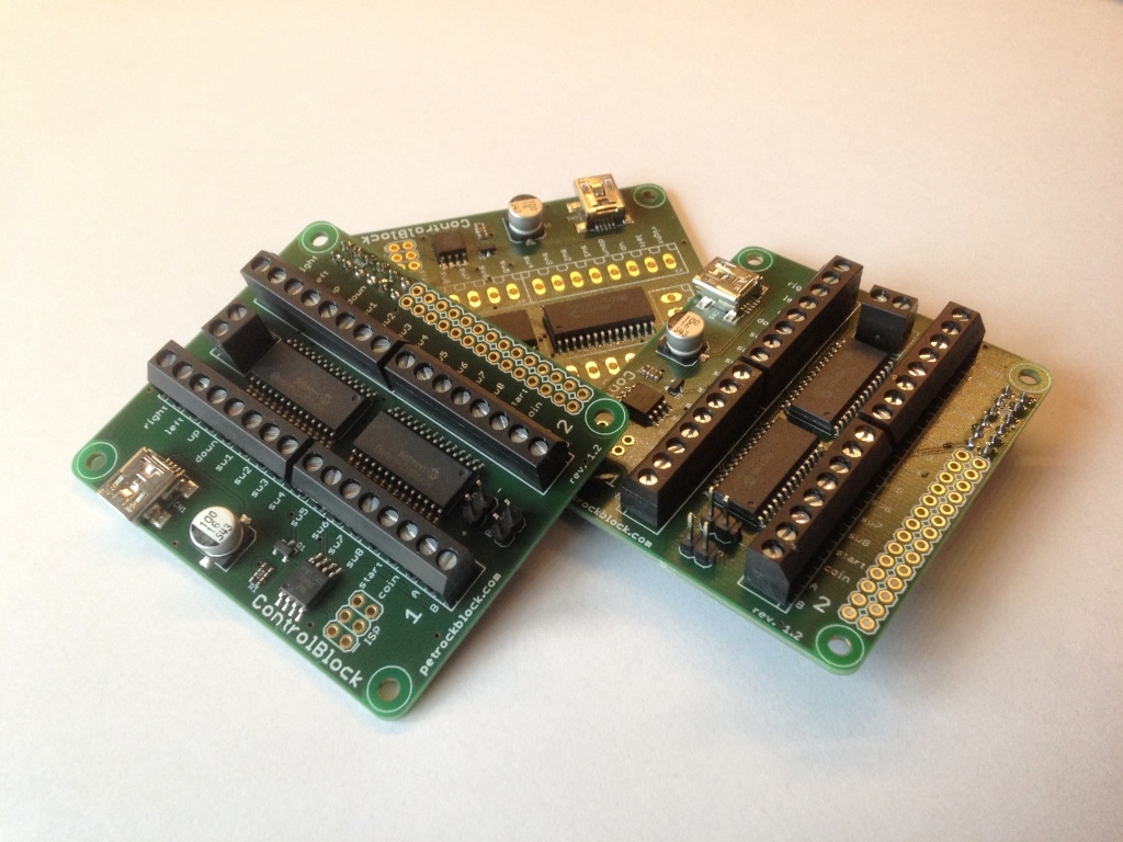
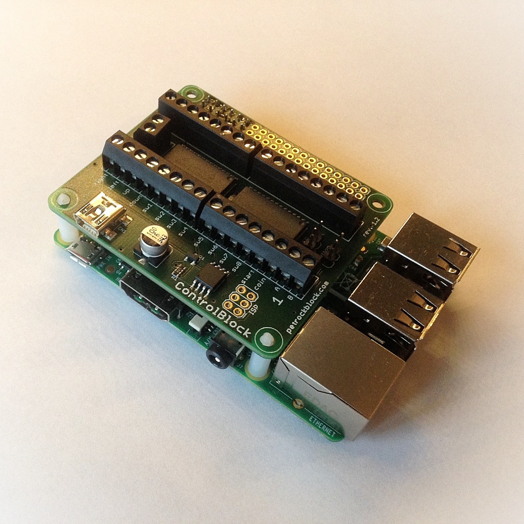
The ControlBlock is an add-on board for the Raspberry Pi (version 1, 2, and 3) models A+ and B+. It provides a microcontroller-based power-switch functionality as well as two General Purpose Input/Output (GPIO) Expanders with overall 32 pins so that you are able to connect quite anything you like to it.
Besides the hardware itself, a driver software is presented here, that allows for an easy installation and configuration of the ControlBlock functionalities, especially the connection of game controllers. Currently, the driver supports these game pad types:
- Arcade Controllers
Connect any controllers that are based on microswitches and the driver will map these either to two distinct game pads or to keyboard presses with MAME layout, which can be seen as the de facto standard in this field. - SNES Controllers
The driver also supports the polling scheme of Super Nintendo Entertainment (SNES) controllers. Currently, the driver supports up to two SNES controllers that can be attached to the ControlBlock. - NES Controllers
Since Nintendo Entertainment System (NES) controllers and SNES controllers are so similar in their hardware, the driver also supports up to two NES controllers.
The sources of the driver are publicly available at Github and can be further enhanced to support additional controllers in the future.
In the following, details are given for the individual features that are mentioned above. Functionalities, dimensions, and hardware interfaces are described first. Then, the assembly is described in more details. After that, the configuration and a demonstration video is presented. A conclusion is given at the end of this article.
Functionalities
The ControlBlock provides two main functionalities that can be used independently from each other:
- Power Switch
The Raspberry Pi comes without a power switch. As soon as you plug the micro USB cable into the RPi, it turns on. If you want to shutdown the RPi, you need to call a shutdown command to to bring the system into a state in which you can safely remove the USB cable again.
The ControlBlock provides a connector for a toggle switch to control the power supply of the RPi. Furthermore, it provides a connector for an LED to indicate whether the RPi is off, booting, running, or shutting down. The power supply is controlled by a tiny microcontroller that monitors the button state as well as the state of the RPi and switches a MOSFET accordingly. This means that there is no need anymore to plug and unplug the USB cable from the RPi if you want to completely turn your RPi off. -
General Purpose Input/Output and Game Controllers
The 2×40 pins header of the Raspberry Pi already comes with a bunch of GPIO pins that can be used for all kinds of things to control and sense. However, these pins go directly into the main controller of the RPi and there is no further circuitry protection. Also, if you want to attach a set of arcade controllers, this task can become quite troublesome. The ControlBlock comes with two GPIO expanders MCP23017: Overall, you have 32 additional GPIO pins that can be controlled via the I2C interface of the RPi. The GPIOs can be accessed with terminal blocks that also provide cable protection. And if you accidentally create a short circuit you do not have to fear to fry your whole Raspberry with that then.
Also, if you want to connect your RPi to any kind of game controllers, you have to decide which GPIO pins to use and you must adapt your driver software such that exactly these pins are controlled. The ControlBlock makes the task of connecting game controllers to the Raspberry Pi very easy: The ControlBlock PCB is clearly marked with pin outs for players 1 and 2 and the provides driver software for the ControlBlock can easily be configured for different controller types.
Dimensions and Interfaces
Dimensions
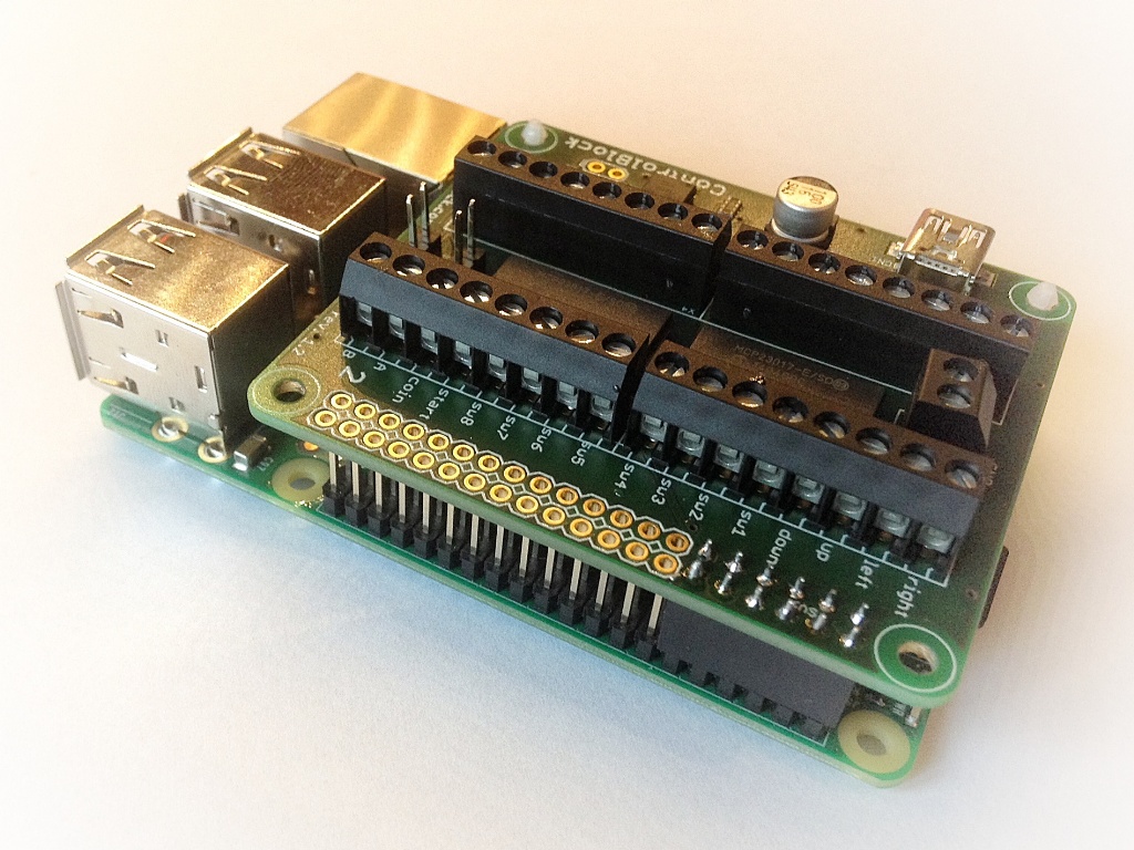
The dimensions of the ControlBlock PCB are chosen such that it exactly matches the mounting holes of the Raspberry Pi models A+ and B+. The ControlBlock PCB comes with the same round corners as the Raspberry itself. Of course, these round corners provide no further functionalities, but give the whole setup a neat look. Regarding the GPIO usage the ControlBlock is attached to the first 2×6 pins of the Raspberry Pi GPIO header.
The ControlBlock does not fit the Raspberry Pi models A and B. The reasons for this are the composite out connector and the missing mounting holes of the Raspberry Pi models A and B.
Hardware Interfaces
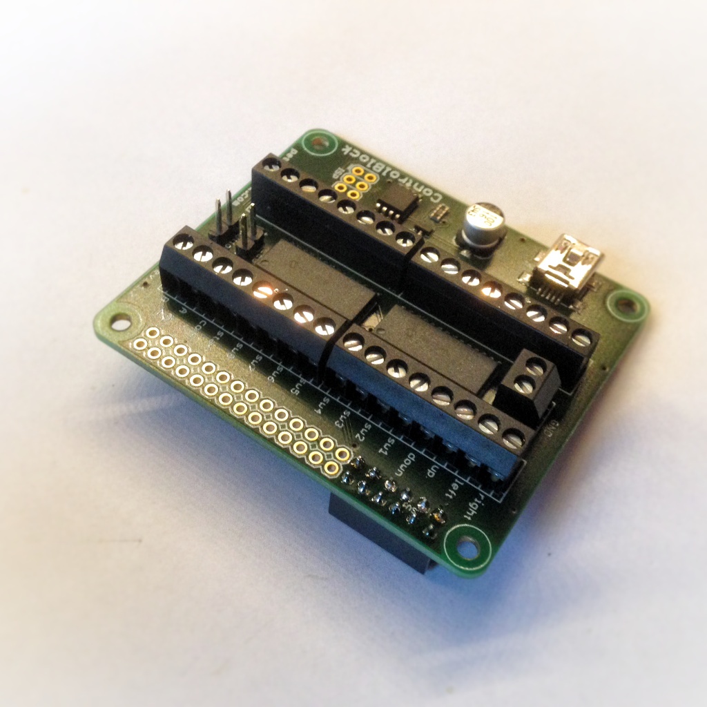
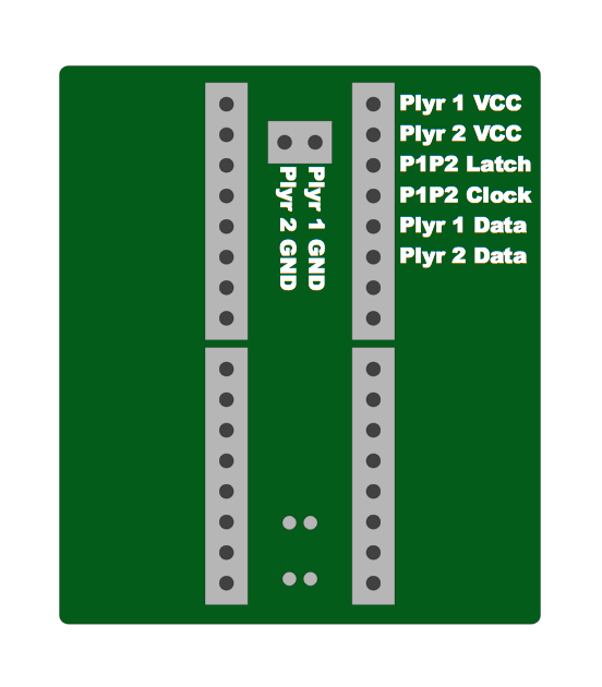
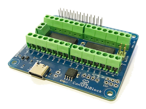
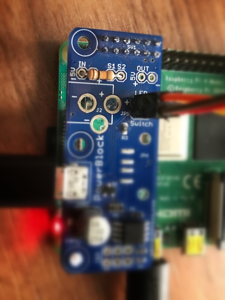
Here is a top-view of the ControlBlock PCB: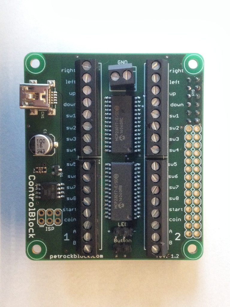
The hardware interfaces of the ControlBlock are described in the following:
- 2×6 pin female header as connector to the Raspberry Pi
The ControlBlock PCB is attached to the Raspberry with a 2×6 pin female header. This header makes use of pins 1 to 12 of the J8 header. This header is used for connecting the voltage and ground pins as well as the I2C pins between the RPi and the ControlBlock. The PCB is prepared for breaking out all other pins of that header so that you can easily access all other pins that are not used by the ControlBlock. -
Micro or B-Type: USB Connectors for the power supply
The first version of the ControlBlock had a USB mini connector. Because so many people asked for it the ControlBlock got a USB Micro connector now. That means you can simply use your existing USB Micro cable. The USB Micro connector comes by default with the ControlBlock. If you would like to use a bigger USB connector, you can optionally solder a USB-B socket to the ControlBlock! This should give you the flexibility that you need for your project. -
Pin Outs for 5V Supply Voltage and Ground
If you do not want to use USB connector, GND and the 5V supply voltage can also be accessed via two pins so that you could use batteries or whatever you like. -
Pin Out for a Toggle Switch
To control the power state of the Raspberry Pi the ControlBlock provides an interface for attaching a toggle switch. The on-board microcontroller monitors the state of that switch as well as the one of the Raspberry. -
Pin Out for Status LED
The current power state can be indicated with a 5V status LED that can be attached to the two pins that are provided by the ControlBlock. These states can be “off”, “booting”, “on”, and “shutdown”. The different state are indicated with easy-to-distinguish static and pulsing patterns. -
2×16 GPIO pins
Overall, the two GPIO expanders provide 32 GPIO pins for arbitrary usage. With revision 2.X of the Raspberry Pi, these pins can be accessed via the SPI interface of the Raspberry Pi. With revision 1.X of the ConterolBlock, these pins can be accessed via the I2C interface with the I2C addresses 0x20 and 0x27.
Alternatively, to manually access the pins you can use the provided ControlBlock driver software to easily connect and poll various game controllers. For this, the top silkscreen of the ControlBlock PCB is marked with pin outs for players 1 and 2. -
In-Service Programmer (ISP) pin-out for ATTiny
The Power Switch logic is realized with the help of an Atmel ATtiny85 microcontroller. If you want to you have the possibility to access the microcontroller with the ISP header. In this way you could reprogram the microcontroller with whatever functionality you like. -
GPIO pins used by the ControlBlock
The ControlBlock revision 2.X uses these GPIO pins of the 40-pin header of the Raspberry Pi: 3.3V (pin 1), 5V (pin 2), GPIO 17 (pin 11), GPIO 18 (pin 12), MOSI (pin 19), MISO (pin 21), SCLK (pin 23), CE0 (pin 24).
Assembly of the ControlBlock
The ControlBlock consists of SMD as well as of THT components. The THT components consist of these parts:
- 1x 2-pin female terminal block
- 2x 2-pin male header
- 1x 2×6-pin female connector
- 4x 8-pin female terminal block
These parts are shown in the following image: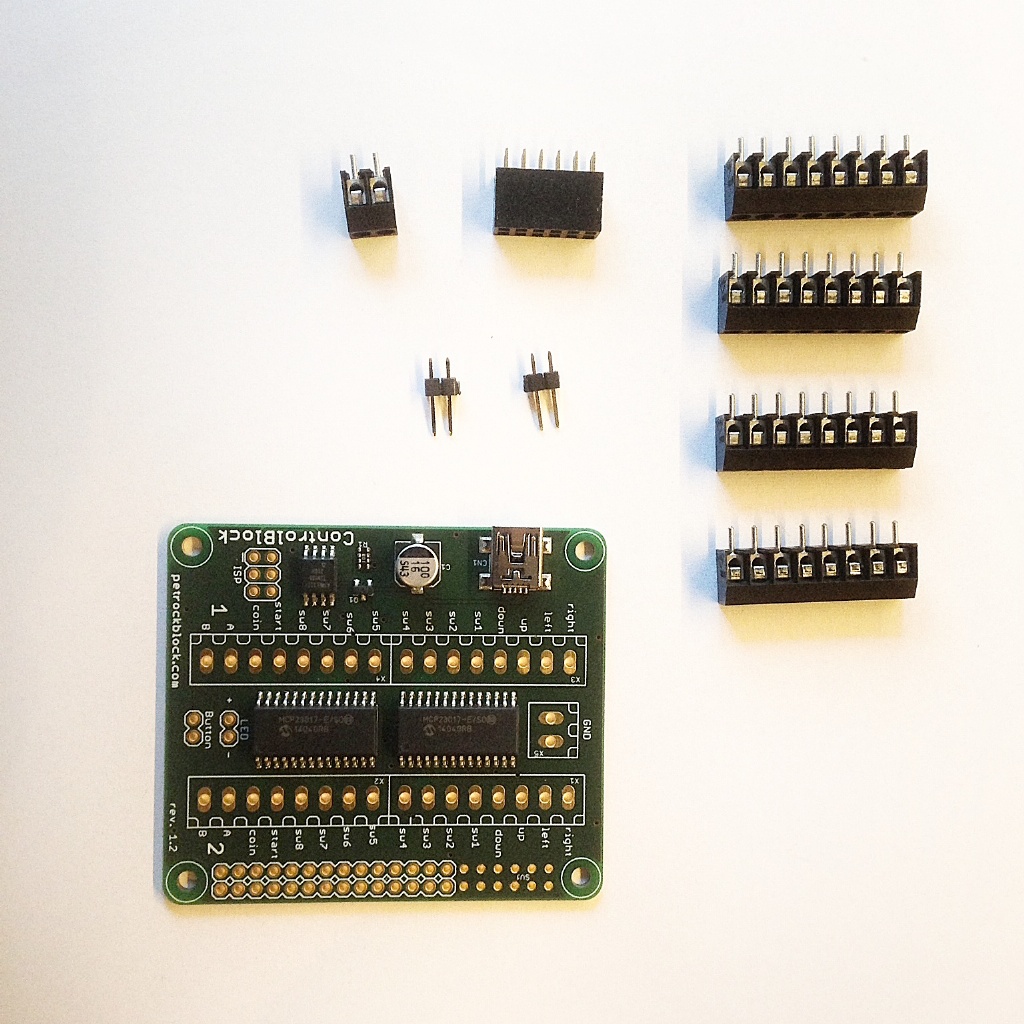
The assembly of the THT components is done in a few steps, which are described in detail in the following:
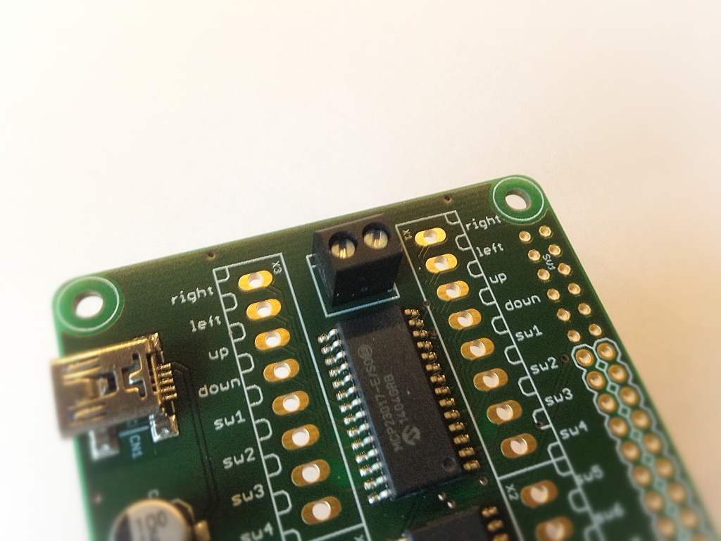
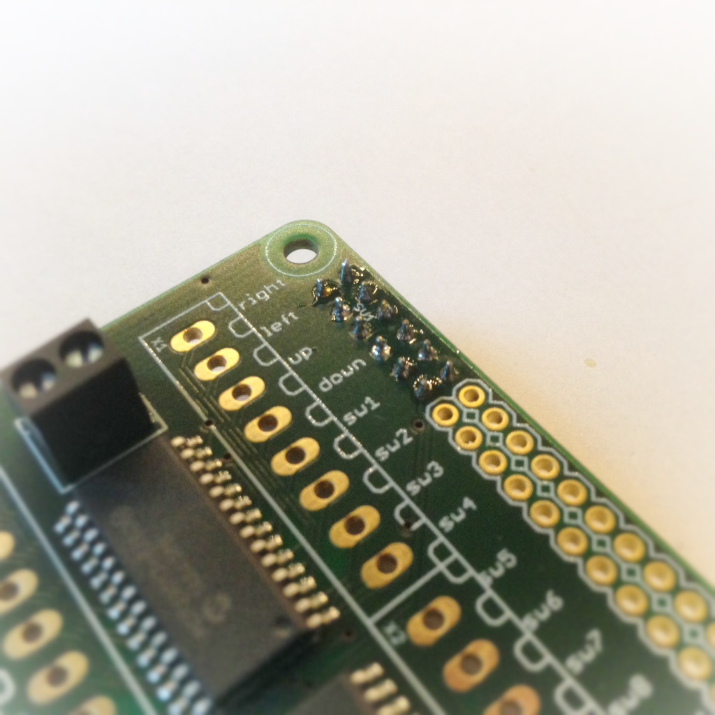
- Solder the 2-pin female terminal block on the top side (i.e., the side with the white marking print) of the ControlBlock. Take care for the correct orientation of the terminal block!
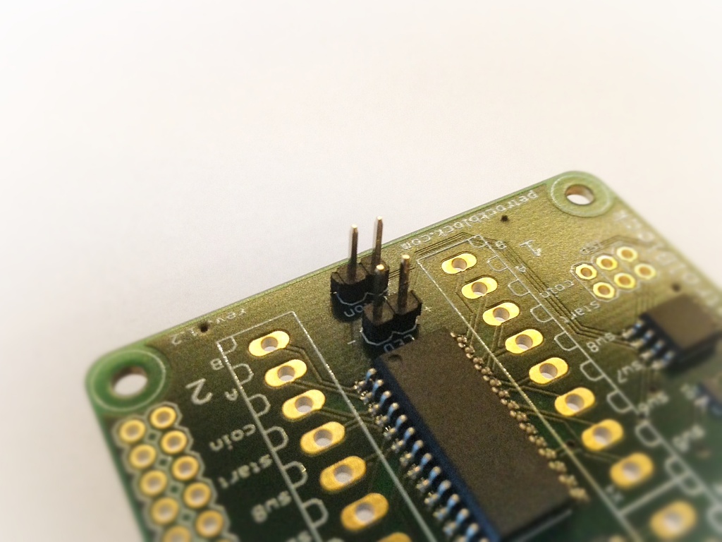
2. Solder the two 2-pin male headers for the button and the status LED. Note that you might to adapt this step according to the button and/or the LED that you want to use with the ControlBlock.
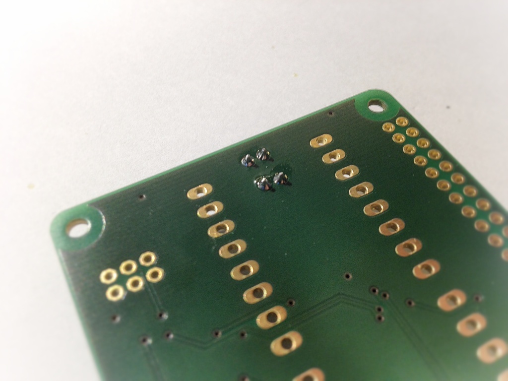
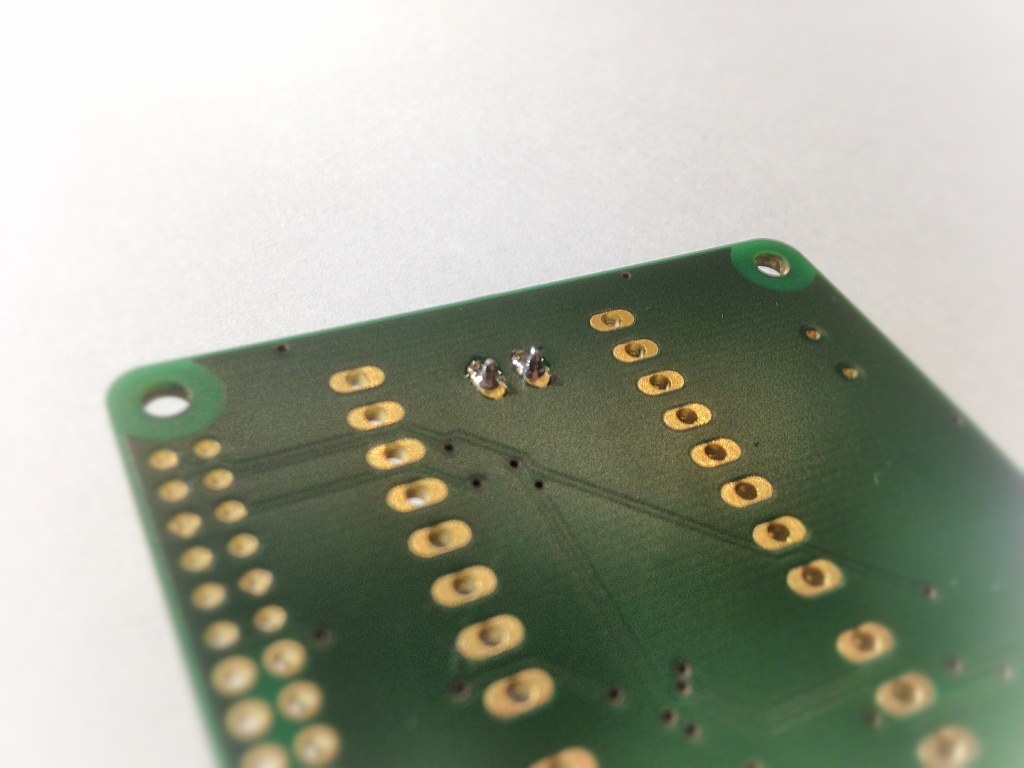
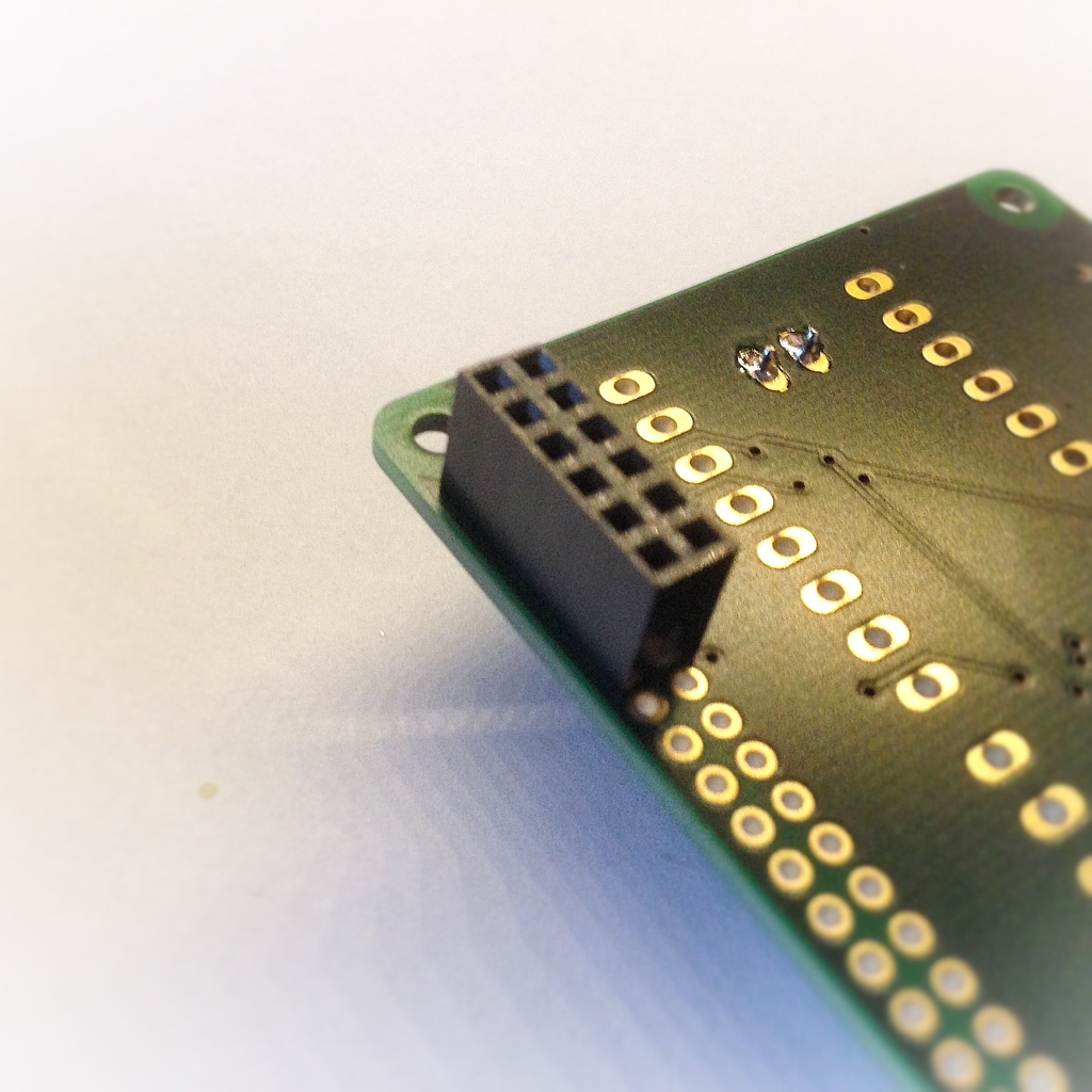
3. Solder the 2×6 female pin header on the bottom side of the ControlBlock (i.e., the side without the white marking print)
4. Solder the first 8-pin terminal block on the top side of the ControlBlock. Take care for the correct orientation of the terminal block! First, solder a single pin and check the resulting alignment of the terminal block. If the terminal block is placed well, continue with the other seven pins.
5. Solder the other three 8-pin terminal blocks in the same way as you did with the first 8-pin terminal block.
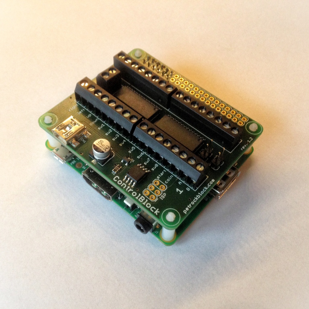
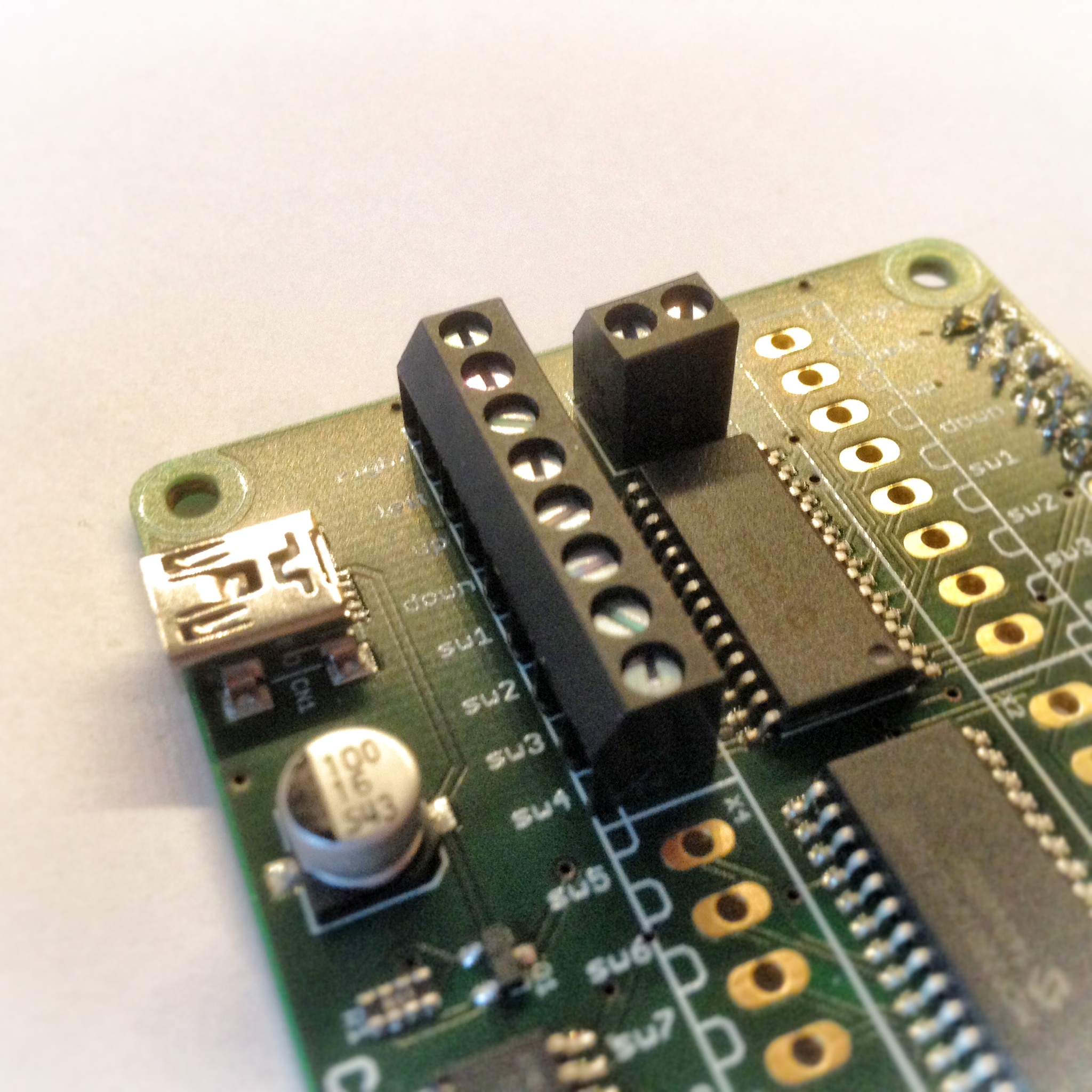
The fully assembled ControlBlock should look like this:
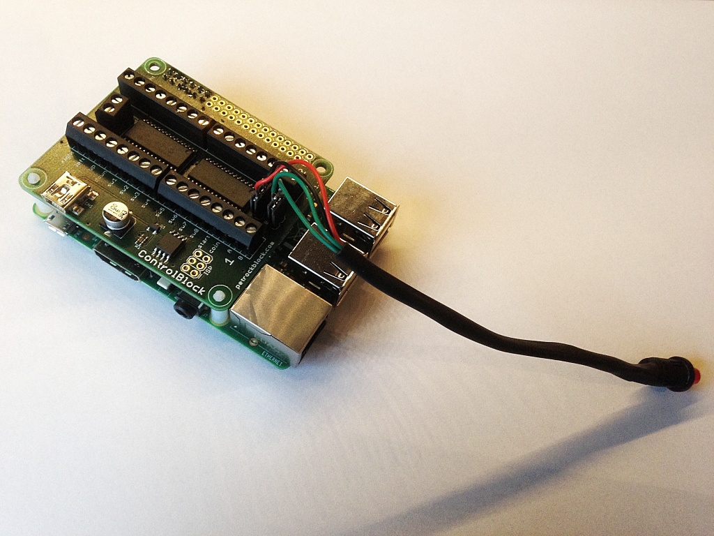
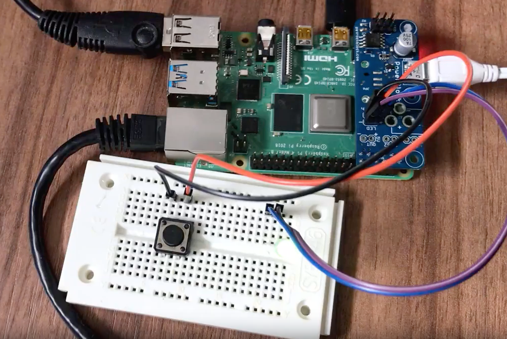
Attaching a Power Button
To turn the Raspberry Pi on and off with the ControlBlock you need to attach a toggle switch to the two button pins on the ControlBlock. Technically speaking, the microcontroller on the ControlBlock looks, if the two button pins are connected or not. If they are connected, a GPIO pin of the microcontroller on the ControlBlock is pulled to GND and interpreted accordingly.
- It is important that you use a toggle switch and not a momentary button with the ControlBlock. Otherwise the Raspberry Pi will be turned off again right after booting.
- If you do not want to use the power switch functionality you can disable this in the configuration file /etc/controlblockconfig.cfg by setting “powerswitch”: false.
- The power switch circuitry of the ControlBlock leads to a tiny voltage drop and we made the experience that a good quality power supply and a good quality USB cable are mandatory for a working setup. If unsure, we can recommend the official Raspberry Pi Power Supply.
Attaching a Status LED
The ControlBlock has pin outs for an optional status LED that indicates the power state of the Raspberry Pi. You can directly attach an LED to the pins that are marked with “LED”. You need to pay attention to the polarity of the LED: The LED pins are marked with “+” and “-” for that.
The LED will blink in four different patterns that depend on the power state of the Raspberry Pi:
- Off: The LED is simply off.
- Booting: The LED slowly fades in and out.
- On: The LED constantly stays on.
- Shutting down: The LED fades in and out twice as fast as during boot up.
How to attach Arcade Buttons, Joysticks, Gamepads
The cables from the arcade buttons, joysticks, as well as from the (S)NES gamepads are connected to the ControlBlock via the screw terminal blocks. You need a slotted screwdriver with a maximum width of 2.5 mm for that. Detailed instructions for the individual controller types are given further below.
Software Setup and Configuration
The GPIO ports of the ControlBlock can be accessed via the I2C interface of the Raspberry Pi. The addresses of the two GPIO expanders are 0x20 and 0x27.
The power switch functionality of the ControlBlock is controlled with the GPIO pins 17 and 18 of the Raspberry Pi:
- Pin 17 can be used to indicate the power state of the Raspberry Pi. This pin is read by the ControlBlock”s microcontroller to control the on-board power switch.
- Pin 18 can be read by the Raspberry Pi to get status of the button that is attached to the ControlBlock.
The ControlBlockService is an open-source driver for the ControlBlock. It provides a service for interacting with the power button signals as well as for mapping attached game controllers to corresponding game pad devices on the Raspberry Pi. The installation only takes a few steps and can either be done completely from command line or half-automatically with the help of the RetroPie-Setup Script. In the following, these two methods are described in more detail.
Command-Line Installation
Before you start with the installation of the ControlBlock driver, make sure that the SPI-interface (in case of ControlBlock rev. 2.X) or the I2C-interface (in case of ControlBlock rev. 1.X) is enabled. You can do this via the tool raspi-config in the “Advanced Options” menu. Enable the interface and let the kernel module be loaded by default. Reboot your system to let the changes take effect.
The command-line installation consists of these steps:
- Installing required packages
- Fetching the latest version of the ControlBlock driver and service from the public repository.
- Compiling the driver binary.
- Installing the driver binary.
- Installing the service.
Here is a step-by-step guide:
- Eventually: Download and copy the RetroPie SD card image version 3.5 to the sd card
- Do not connect any other (USB) controller to the Raspberry for now to avoid any unnecessary interference
- Connect the power supply and the switch with the ControlBlock and switch on the Raspberry
- When EmulationStation has loaded and shows the controller configuration, press F4 to get to the command prompt.
- Alternatively: Connect to the Raspberry Pi via SSH to get to the command prompt
- Run „sudo raspi-config“, select „Advanced Options“, select „SPI“ and enable the SPI interface and the SPI kernel module on boot by default by selecting „Yes“ in the following two screens.
- Exit raspi-config by selecting finish and select „reboot“ when asked for it.
- Again, press F4 in EmulationStation to get to the command prompt or connect to your RPi via ssh
- Update the apt package cache: sudo apt-get update
- Install any APT updates: sudo apt-get upgrade -y
- Reboot (IMPORTANT, otherwise we might get a modprobe error) via “sudo reboot”
- Install necessary packages: sudo apt-get install -y cmake g++-4.9 doxygen
- Clone the ControlBlock driver repository:
git clone --recursive https://github.com/petrockblog/ControlBlockService2.gitIf you have revision 1.X of the ControlBlock use the commandgit clone https://github.com/petrockblog/ControlBlockService.git - Change into the driver folder: “cd ControlBlockService2” (or “cd ControlBlockService” for rev. 1.X)
- Build Makefile: mkdir build && cd build && cmake ..
- Compile the driver: make
- Install the driver: sudo make install
- Install the service so that the driver is loaded on boot: sudo make installservice
DONE
- You can now configure the ControlBlock service by editing its configuration file via „sudo nano /etc/controlblockconfig.cfg“.
- After changing the configuration, you can reload the service via „sudo service controlblockservice restart”
- You can test your attached controller(s) with the tool jstest, e.g., with „jstest /dev/input/js0“ (Exit with Ctrl-C)
This video demonstrates the above steps:
Using Arcade Controllers with the ControlBlock
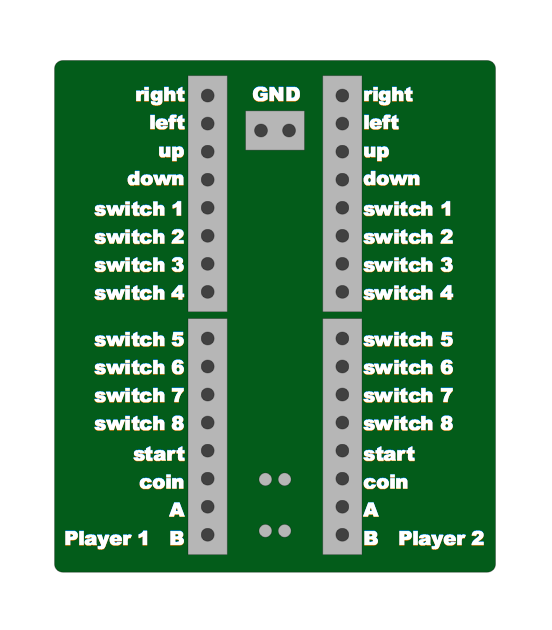
The ControlBlock comes with silkscreen indicators that describe a default pin out for arcade controllers: You can connect two joysticks and 12 buttons for each of the two players:
The ControlBlock service can be configured in two different ways when using arcade controls:
As one option it can be configured such that it provides two game pad devices in the system, one for each player. To do so, the configuration in the file /etc/controlblockconfig.cfg must set “gamepadtype” to “arcade”:
“gamepadtype” : “arcade”
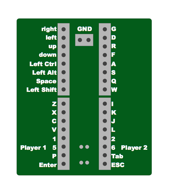
As another option the ControlBlock service can be configured such that it provides a virtual keyboard with the de-facto MAME standard. To do so, the configuration in the file /etc/controlblockconfig.cfg must set “gamepadtype” to “mame”:
“gamepadtype” : “mame”
The button mapping is shown in the following diagram:
Using (S)NES Controllers with the ControlBlock
The ControlBlock can also be used to poll NES and SNES controllers. Here is a diagram that describes the pin out for using NES and SNES controllers with the ControlBlock:
Here is a pin out diagram for NES and SNES connectors:
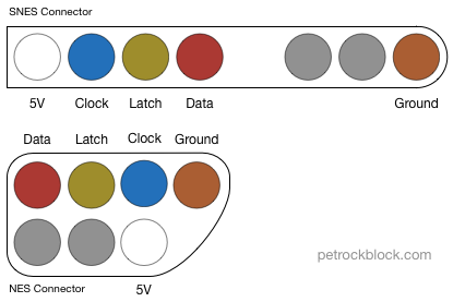
If you want to use a SNES case, here is a diagram that shows the pin out of the original SNES controller front:
In order to poll NES and SNES controllers the configuration in the file /etc/controlblockconfig.cfg must set “gamepadtype” to “snes”:
“gamepadtype” : “snes”
You can also connect a latching reset button to Player-2, Input B. If the button is pressed a virtual ESC-key press will be triggered.
Only one Gamepad
If you want to connect only one gamepad to the ControlBlock you can set the element onlyOneGamepad to true: It enables only one gamepad in the system (e.g., if only Player-1 buttons are wired to the ControlBlock in your setup, this prevents a ghost gamepad from being selected as default player 2 in retroarch)
4-Player Extension
The driver can handle up to two ControlBlocks. This means that you can stack two ControlBlock on top of each other to have inputs for four players. To do so make sure that you set different addresses for each of the ControlBlocks. You can set the address of each ControlBlock by setting the two solder jumpers of each ControlBlock accordingly. The values of the solder jumpers have to be set in the configuration file with the elements SJ1 and SJ2. Also, you have to enable the second ControlBlock by setting the element enabled for the second ControlBlock to true.
Power Switch Functionality
To enable or disable the power switch functionality you can set the element powerswitchOn to true or false:
- true: Activates the handling of the power switch signals of the ControlBlock.
- false: Deactivates the handling of the power switch signals of the ControlBlock.
Video Demonstrations
Power Switch
The following video shows the power switch functionality of the ControlBlock:
Arcade Controllers
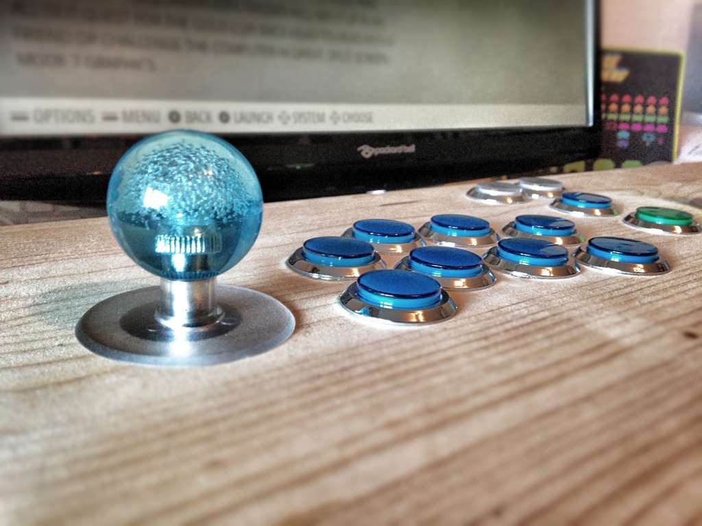
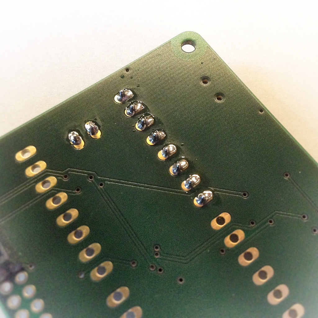
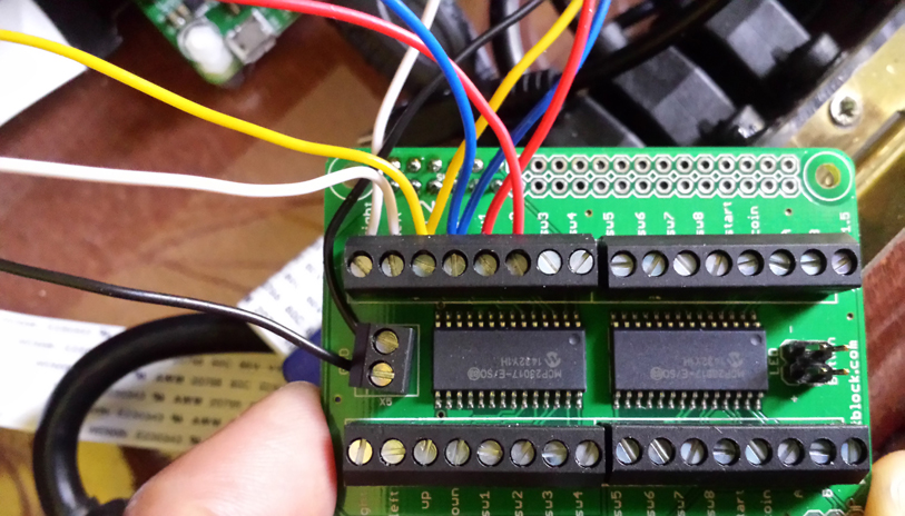
The the following demonstration video shows arcade controllers for two players that are mounted on a simple wooden console. The bottom of it looks as following:
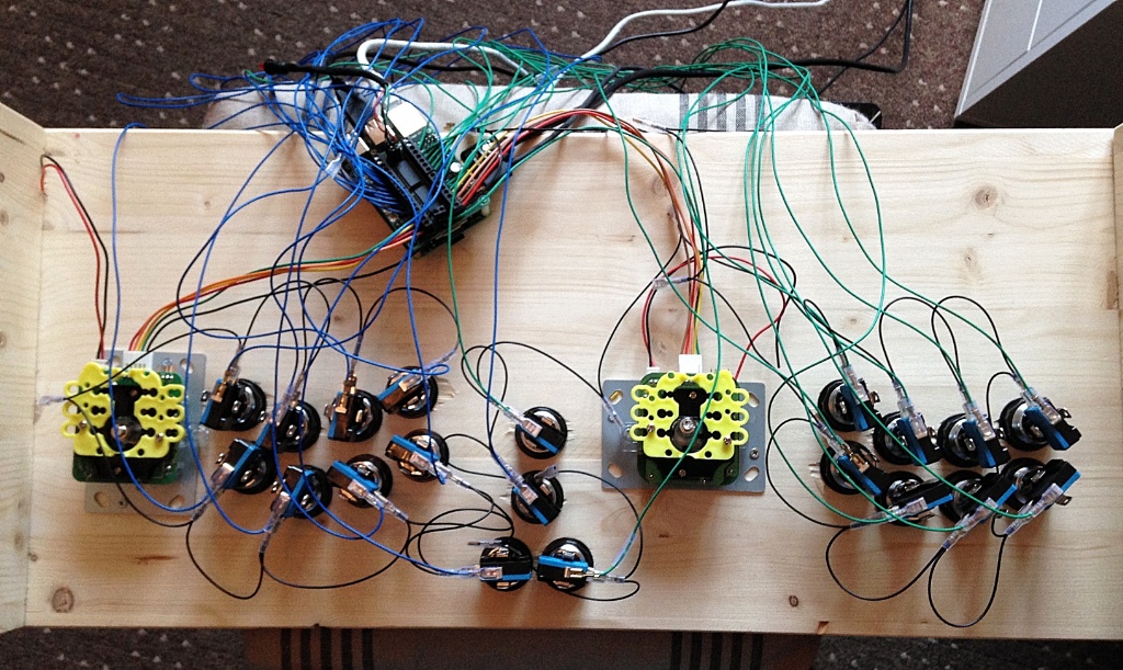
This video shows the controllers in action:
SNES Controllers
This video shows the ControlBlock with SNES controllers attached to it:
Conclusion
The ControlBlock is an extension board for the Raspberry Pi (TM). The two key features of the ControlBlock are
- a power switch functionality and
- general purpose input/output (GPIO) pins ready to use, e.g., for connecting arcade or SNES controllers.
The power switch functionality allows to turn on and off the power to the Raspberry Pi with a toggle switch. Therefore, a toggle switch can also be connected to the ControlBlock. There is also a connector for a status LED that indicates the power status of the Raspberry Pi.
The GPIO pins can be accessed from the Raspberry Pi via the I2C interface. The ControlBlock makes it very easy to connect arcade controllers for up to two players. The open-source driver for the ControlBlock can be configured for various controller types. It supports, e.g., arcade controllers that are mapped to game pad devices, as well as a mapping to a MAME keyboard configuration. The ControlBlock also supports, e.g., the polling of SNES and NES controllers so that it also provides the functionality of the RetroPie GPIO Adapter.
If you are interested in getting the ControlBlock for your project, it can be ordered at the shop.
No, that is not possible – the circuit of the ControlBlock only supports one LED. However, you could use the status LED output to also drive a relay that, in turn, drives the LEDs for the buttons.
Is it possible to drive 8 LED’s (5 volt) in parallel from the status led pinout and use a common ground pin with the arcade button pins?
I wanna light my arcade buttons but use one ground pin for the Switch and the LED.
We have fixed that with the recent update of the ControlBlock driver. Re-installing it will make the shutdown fast again (besides some more improvements), https://github.com/petrockblog/ControlBlockService2#controlblockservice2.
Hi, since recent version of Retropie, the control block takes almost 3 minutes until shutting down / turning off the Pi. It used to take only seconds. New normal?
The ControlBlock supports both types of joystick modes.
Hi, did you use a 4way joy or a 8way ? In the first case can I use a 8 way and setup properly? Thanx
Did you already look at the step-by-step guide from https://github.com/petrockblog/ControlBlockService2#building-and-installation?
Whenever I try to use the ‘make’ command after doing all other stuff it says: ‘make: *** no targets specified and no makefile found. stop.’ I don’t know what to do. Please help!
That feature was recently added and is now supported by the ControlBlock driver, see also https://github.com/petrockblog/ControlBlockService2#configuration.
Yes, they do.
Does anyone know if the ControlBlock supports 4 player arcade? I was about to order it and now I wanna hold off until I know it works.
Do these instructions still apply to retropie 4.0?
I do not know. It would be interesting to hear about some experiences, though!
Yes, you can continue to use any USB device.
If you were to wire this to SNES controllers, can you continue to use the USB ports or BT for additional/other controllers? Or is it an either/or situation?
Hi, is this block compatible with orange pi one ?
As long as the overall current is not greater than 3.7 A the ControlBlock can be used to driver other devices besides the Raspberry itself. However, in case of LEDs, an LED driver might be preferable.
Hello! I just got my ControlBlock in the mail!
I was wondering if it can support LED arcade buttons that light up?
I currently have 4-terminal microswitches with embedded LEDs.
I would like some unstructured instructions for attaching coin mechs. Are these available?
I would recommend a heat sink of 8 mm height as maximum.
The ControlBlock and the Raspberry Pi 3 are fully compatible with each other!
Great article! A quetion: I’ve a raspberry pi 3 model B, the
ControlBlock is not usable on my model or i only can’t obtain a
beautiful result combining my model with this ControlBlock? Thx
If using the control block on the RPI 3B what size heatsink would you recommend using? I am not sure how big the gap is between the control block and the RPI.
Sounds as if the switch is wired backwards.
I built my raspberry with the ControlBlock in my SNES and connected the power switch. but i made the software setup with the switch turned off now the system boots the otherway arround (when i turn the switch to off it boots). can i restore it in the config? thx for your help
The ControlBlock is fully compatible with the RPi 3 b.
I just ordered this for a Raspberry pi 3 b. Will it fit? I see no detail the dimensions. Is there a 3 b+ available?
Also has anyone found a case with a fan this will fit into?
I just ordered this for a Raspberry pi 3 b. Will it fit? I see no detail the dimensions. Is there a 3 b+ available?
Also has anyone found a case with a fan this will fit into?
Awesome thanks i will def. add the fan on the side
The ControlBlock is stacked on top of the Raspberry Pi, so there is only a limited space between the CPU and the ControlBlock. However, it is enough to add a heatsink. A fan would need to be mounted at the side of the Raspberry.
Any toggle switch will do. The one showed in this article is the one from http://www.reichelt.de/Drucktaster-Druckschalter/S-9156-RT/3/index.html?ACTION=3&GROUPID=7586&ARTICLE=44438&OFFSET=500&SID=12V5EXXqwQATQAACPlsIw60cfdafcf30200ae7937a68c7979b5bb&LANGUAGE=EN.
If i have my RPI 3 and i add the control block to it, is it possible to add heat sink and a mini fan or is that not even something considerd? Im new to this. Would that be too much? Also where can i get the same toggle switch?
Hi Thomas, yes – you can use the original SNES power switch and LED. All GPIO pins are accessible also with the ControlBlock attached, so that you should not have any problem with further custom circuit!
Did this ever get added? I would love to convert an existing 4 player arcade cabinet
I just saw photos of the latest revision and it seems that it allows access to pins 1 to 12. Ist that correct? So I could still use those to connect the SNES reset button and perform a soft reset, right?
Hi. I’m planning to build my own “RPi in a SNES case” project and want to buy a ControlBlock for this as it seems to make it a lot easier. As far as I understand it, I can use the original power switch and the original LED with the ControlBlock, right? But what about the SNES reset button? There are many tutorials out there that describe how to build a soft reset circuit but they all use GPIO pins that would be blocked by the ControlBlock, mainly Pins 1, 6 and 7. 1 and 6 are no problem, but Pin 7 seems to be unique. Any idea how I could make the reset button work?
P.S.: I have a RPi 1 Model B+.
The recent version of the ControlBlock gives you access to all GPIO pins of the Raspberry Pi, so you can use all of the pins – including the 5V pin.
I am loving the PowerBlock for use with my RetroPi and was considering picking up an amplifier to use with an 8-Ohm speaker. This should work well since the amplifier requires access to one of the 5V and ground pins and the Powerblock has access to that next to the led and switch pins. I’ve soldered pins there and used them to run a fan thus far. I wanted to hook up SNES ports so have ordered my ControlBlock. It replaces the PowerBlock of course but doesnt seem to give you access to run something to the 5V pin. Will I be able to use this amplifier with the ControlBlock? (https://www.adafruit.com/product/3006)
I have this device and a MiniPac USB device. Which is better to use with a RPi3?
Hi. I built my arcade with this great gadget. Now, I installed Kodi on retropie and I would like use arcade joystick and buttons for control. I tried with Joymap version 0.3, but don’t recognized arcade controls events. Somebody has a sugerence?
Thanks and luck with your proyects.
Thanks a lot ! Thought i had the controlblock rev 2.X :-D
The command-line instructions at https://www.petrockblock.com/2014/12/29/controlblock-power-switch-and-io-for-the-raspberry-pi/#Command-Line_Installation had a typo for ControlBlock rev. 1.X. Please make sure that you install the correct driver, which is located at git://github.com/petrockblog/ControlBlockService.git in case of rev. 1.X ControlBlocks.
As far as I know there is no regional lock on the controllers. the command-line instructions at https://www.petrockblock.com/2014/12/29/controlblock-power-switch-and-io-for-the-raspberry-pi/#Command-Line_Installation should point you to into the right direction.
I can’t on fresh installed retropie 3.7 with control block rev 1.6.
I followed all the steps without errors or mistakes, juste deactivated powerswitch functionality in controlblockservice.cfg.
Am i missing something ?
Player 1 & Player 2 VCC is for 5V right ?
Maybe an error on my wiring …
Hi!
Thans for this excellent addon! :D
I have one question, I am using a Super Famicom controller board and SFC pads.
I’ve soldered the stuff like the image above, but I can’t make the pads work. The switch and LED work as they should tho. Does this have something to do with regional lock on pads? I remember that NTSC pads aren’t compatible with PAL consoles. Any help would be great, as I can’t find a solution. :(
Actually, the hardware of the ControlBlock comes with a stackable header and all necessary signal lines are designed so that multiple ControlBlock can be stacked.
However, the ControlBlock driver software still needs some additions for that. I could add this functionality within the next 2-3 weeks.
Is it possible to stack these to extend the number of controllers to 4? I’m looking to build a 4-player arcade cabinet.
I don’t think so, I suppose any spare GPIO would do (unless another commenter has any better recommendations). I believe that INTA and INTB can be setup to be OR’d together, so you could hook up just 1 interrupt if you wanted to save GPIOs, but it then again it might be nice to have both interrupts available.
It would mean it would be possible to have the controls interrupt driven, rather than polling the chips, perhaps using the MCP23008 driver (I believe it’s included in Raspbian) which supports MCP23017 and MCP23S17. Though according to http://lxr.free-electrons.com/source/Documentation/devicetree/bindings/gpio/gpio-mcp23s08.txt the driver only supports interrupts for I2C chips atm, so maybe it wouldn’t be ideal for MCP23S17 at the moment.
The current revision does not have any interrupt lines from the MCP23017s connected to the Pi-GPIOs.
that is an interesting idea for the next revision, which is planned to be produced within the next two to three months. Would you have a preference regarding the connections?
I was wondering whether any of the interrupt lines from the MCP23017s were linked up to any Pi GPIO?
It is meant for the coin button that you can assign, e.g., in MAME.
No, we do not sell them. However, you can get them from SNES extension cables quite cheap.
I have the control block. Do you sell the SNES adapter board as well? I cannot locate replacement SNES connectors (for cheap that is) from my usual source (eBay).
I See “Coin” Pin, How to Use It ?
Without knowing the details of that switch, I assume that you can simply connect the middle the on of the outer pins with the „switch“ pins of the ControlBlock.
Curious to know if anyone could help me figure out how to do the power switch thing with a 3 pronged rocker switch instead?
It works! I think I have an error in my wiring, but that is for me to work on. An awesome addition to the Pi, for sure. Danke.
I found that one important change did not make it into the yesterday’s updates of the ControlBlockService2. That is fixed now, sorry!
Thank you! I reformatted and started from scratch. I got a different reason for error#2 this time. Also, if it helps diagnose, my switch also does not work. I posted a pic for reference. I feel like I am missing something simple…
You will probably like the PowerBlock:
https://www.petrockblock.com/2015/07/04/powerblock-another-power-switch-for-the-raspberry-pi/
:-)
The ControlBlock service installs one or two (depending on the configuration) controllers in the system, which appear, e.g., in /dev/inputs/. Usually, they are players 1 and 2. Additional controllers just appear as other controllers in that folder. How the emulators react on these variety of controllers must be configured in the emulator configuration, I guess.
Certain things changed with the Raspbian version “Jessie” in comparison to “Wheezy”. I have pushed the needed updates for the ControlBlockService2, which fix these issues!
Anyone having issues with “install error #2”? It is looking to update a file during “sudo make installservice”, but the target file is not there. Directory tree enabled in Retropie and all APT updates completed. Also, where can I install this via the semi-automated script mentioned above? Thanks for any help.
How down the ControlBlock work with other USB controllers and the hot-swapping ability you have programmed intro RetroPie? I would like to build a 2-player arcade box where I could use only the arcade sticks and buttons except when I feel inclined to plug in retro style usb game pads. I want the arcade sticks/buttons to be player 1&2 unless I add USB gamepads, then I want them to become player 1&2. Will this functionality work with the ControlBlock?
How would one go about doing this? I have zero coding knowhow :)
I used a joystick and buttons kits from arcadeworlduk.com.
What joysticks and buttons did you use?
I have my raspberrypi power supply hooked up to my TV via USB. Once I hit the power button on my remote raspberrypi boots up and vice versa wwhen I turn my TV off. It’s a simple solutions to the switch problem.
Tobias,
Have you resolved your issue with the second set of arcade controls not working? I just recently installed the controlblock and finally can play most games, but with only one sit of controllers. Two people can play, but with only one set. I am not sure where to make any changes. I don’t want to make any changes to retroarch config file cause that may take me back several steps.
Have you had any luck?
A bit late, but the PowerBlock (https://www.petrockblock.com/2015/07/04/powerblock-another-power-switch-for-the-raspberry-pi/) is exactly that :-)
Can’t really find any help online. But thanks for your help anyway.
It can be done with this setup. My friend did it before. But because I’m starting again with a fresh SD-Card, I don’t know how to set up the arcade controls.
All right, I see. Sorry, but I do not know how to do that easily. I am sure there are other customers of that board that have similar things in mind and discuss this in the forum of the distributor or so.
The ControlBlock comes with a dedicated ControlBlock service that does this button-key mapping …
The setup is that the Slice of PI/O board is hooked up to the Pi via GPIO. The arcade buttons are -obviously- hooked up to the board. I don’t have the ControlBlock if I didn’t make that clear before (sorry). There is some activity as when Emulationstation goes dark due to inactivity, and I press any of the buttons or move the joystick, it goes out of the dimness.
I hope that is sufficient information.
Thanks in advance!
So, you have the ControlBlock and the Slice of PI/O board? I do not understand your setup, I think.
If you have the ControlBlock installed, you can set the gamepad type to “mame” so that joystick and button events are mapped to the standard MAME key presses.
I installed everything. But how do you map the arcade buttons to the keyboard buttons. It’s been done before but not by me so I know it’s possible. I need the steps after installation.
Please help!!!
I use the Slice of PI/O board if you wanna know.
Thanks in advance!
Currently, the ControlBlock does not allow this. However, I plan to release a revised version of the ControlBlock that comes with stackable headers so that multiple ControlBlocks can be combined.
I can’t get MAME4ALL to work in RetroPie 3.0 with the “gamepadtype” : “arcade” option. I need to have 2 players with joystick and buttons. The controls work in the menu but not when I get into the games. I have tried to use TAB and change settings for input but the games can’t find the controls. Any help ?
Sounds as if you need to attach a power switch or you need to disable the power switch in /etc/controlblockconfig.cfg.
Also, you need to connect the micro USB ONLY to the ControlBlock, if you want to use a power switch. Hope that helps!?
What have I done wrong when installing ControlBlock drivers and the pie just go halt when rebooting?
Will this control block also provide power to LED arcade buttons? If not, does anyone know how to power LED arcade buttons power with some type of USB connection?
Do you know if I will run into any problems trying to connect 4 arcade joysticks to this? ‘m building a 4 player arcade cabinet. I will have 4 joysticks(16 inputs) and 29 buttons for a total of 45 inputs.
Will the control block allow me to connect 45 button inputs for my 4 player arcade setup?
Thanks again for all your advice, you guys are doing good stuff here!
Hi there,
I’d like to buy your Control Block.
I’m just looking for some advice first.
I’m building a 4 player arcade cabinet. I will have 4 joysticks(16 inputs) and 29 buttons for a total of 45 inputs.
Will the control block allow me to connect 45 button inputs for my 4 player arcade setup?
Thanks so much in advance!
Du brauchst nur ein Netzteil – das selbe, wie Du es für den Raspberry Pi schon benutzt. Das schließt Du am ControlBlock an.
Hallo Florian, sorry mein englisch ist nicht gerade gut, daher in deutsch… Muss ich am Micro USB Connector Strom anschließen? Auch 5V, 2A wie der Rasp? Brauch ich also 2 Netzteile wenn ich den Controlblock benutzen möchte?
I’ve bought ControlBlock but I have two Raspberry Pi 1 Model B. I would like to take advantage of them.
I know that I cannot connect it directly without the Raspberry Pi A+ or B+.
Would it be possible to connect through wires ControlBlock with a Raspberry Pi 1 Model B?
Thanks in advance.
Is it possible to wire an arcade controller (independant buttons & joystick) (P1) and a (S)NES controller (P2) ?
And is it possible to directly wire the (S)NES controller to ControlBlock, I mean without using an adapter like your violet thing on the video ?
Great job btw :-)
There are still enough free ports on the ControlBlock to support that function for SNES mode. If only someone could implement that and create a pull request at https://github.com/petrockblog/ControlBlockService …
Your SNES-controllerboard has a resetbutton. Possible to add that to this board? Putting rpi inside an snes, want both working power and resetbutton..
What is the power draw?
A final question, how do I change the controller order ? In my case I have a wireless xbox360 dongle with 2 controllers, currently loading as Joystick 0 and Joystick 1, these are recognised in Emulation station as gamepad 1 and gamepad 2, this configuration works well as the default controls for MAME (non-libreto) are mapped correctly. My issue arises when I install the controlblock service, on boot up the 2 gamepads presented via the controlblock are now seen as 0 and 1, the xbox controller moves to 2 and 3, in emulationstation 4 gamepads are detected, controlblock is 1 and 2, xbox 3 and 4 ? This breaks my configuration, I cant seem to find an easy way to swap them, xbox as first 2 controllers and controlblock as the next 2 ? Whether I install controlblock first and then teh xboxdrv service or the other way round the device order remains. My guess is that the controlblock loads as a service first so is always the gamepads that are assigned first ? Any ideas on a way to make the swap ? At the moment I have gamepads set to “none” in teh controlblock.cfg …
Glad to hear that :-)
It was actually much simpler, the HDMI-CEC on my Samsung (called Anynet+) had crashed, I discovered that none of my devices worked with HDMI-CEC, unplugging the TV and powering back on fixed it ;-)
I might have a similar situation : when I was testing a development version of the ControlBlock, I made the observation that sometimes my screen lost the signal and said that “The input signal is not supported”. In the end I figured that the low-cost micro USB power cable was the main cause for this. Replacing it with a thicker, better quality one solved the issue for me. Maybe this also helps in your case?
Unfortunately, this is currently not possible. Future revisions of the COntrolBlock might add that capability (which does not help you now).
Yes, stackable female to male headers are the way to go here :-)
Thank you for the response.
So I would just need to purchase additional stackable female to male headers to extend through the remaining pin holes on the control board?
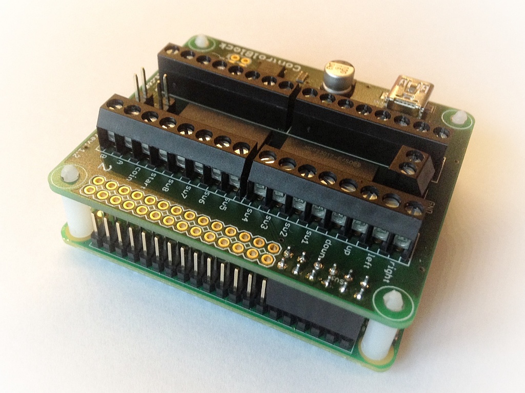
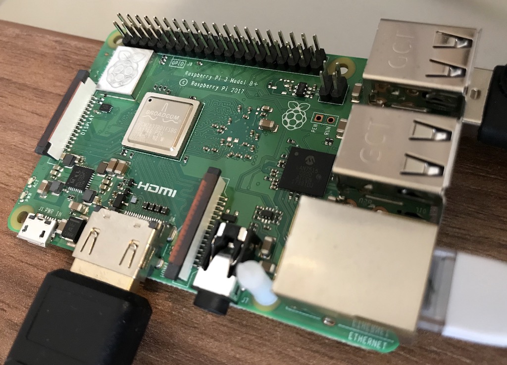
The ControlBlock is prepared such that it lets you install headers for all pins of the RPi. You can see that, e.g., on this image:
https://www.petrockblock.com/wp-content/uploads/2015/12/IMG_0033_Snapseed1024.jpg
How do you access the original gpio pins once the control block is installed? There a header pin out that you can solder to the holes?
There are any way to use 4 controller on the same rasperry pi retropie?
I mean 2 joystick for each controlblock. So, 2 controlblock configured on the raspberry pi
Managed to get my SNES built, RPi2 inside, all working with the power switch, what worked really well with my UK PAL SNES is that I didn’t even need to unsolder the LED, the nintendo LED harness fits straight onto the controlblock ;-) I do however have a question, I seem to have lost HDMI-CEC, previous to installing the controlblock driver and service when I powered on the RPi2 the TV switched on and/or changed to the correct AV channel, after installation of the driver this no longer works ? Have I missed something obvious, brilliant work so far, the RPi SNES looks well just like a SNES, but plays everything under the sun …
Thanks for the reply! I could kick myself for this…I’ll try it as soon as I get home this evening.
You can use the ControlBlock with and without the toggle switch. However, if you use the ControlBlock *without* the toggle switch, you need to *disable* the power switch functionality first in the configuration file /etc/controlblockconfiguration.cfg. This issue can also be found in the forum at https://www.petrockblock.com/forums/topic/controlblock-auto-shutting-down/#post-97774.
I’ve been trying to get my RetroPie and ControlBlock working for several weeks now. Every time I install the controlblock services per the instructions above, my RetroPie crashes and shuts down. I see a warning that appears in the boot sequence which says “WARNING: ‘invoke-rc.d samba reload’ called during shutdown sequence. Enabling safe mode: initscript policy layer disabled.”
Then before it shuts down, the screen says “Deactivating swap..done”
“Unmounting local filesystems…done”
“Will now halt”
If there’s anything else I can provide to help troubleshoot, please let me know. Getting rather frustrating…
EDIT: I do not have the toggle switch installed. Is that necessary for a successful boot?
Ok. Works now. Thank you.
So only the Exit and Coin-Buttons didn’t work…
The power supply cable must be connected to the ControlBlock, if you want to use the power switch functionality of the ControlBlock.
Can you please have a look on my board-entry?
One question: Must the powersupy-cable connected to the RPi2 or to the ControlBlock?
Good idea – thanks!
I delete it here and move it into the forum. Sorry. I thought for support it is better there…
Can you post a picture of your setup here?
What kind of power supply do you have?
Hi,
cool ControlBlock, but something didin’t work:
I’ve installed everything and it might seem to be ok.
So I connect the USB-to power. Then I switch my switch to ON.
The LED fades I see on the screen, that RetroPi is booting. Good
After successful loading I switch to OFF and the RetroPi shutdown. Cool! :)
When I then try to switch to ON again, the LED fades slow, but I didn’t see anything on the screen. Same when I try again switch to OFF!
When I disconnect the power of the USB and connect it again, then it works again as written above.
Any idea?
I am working on a similar project as pixelhersey. My question is: if one of my housemates connects both a NES controler and a SNES controler at the same time and both on the same channel. What is the worst that could happen? Could I fry something (it doesn’t seem to be the case but better safe than sorry)
Argg I have just an old model B
Thanks! New ControlBlocks are being produced in these days. When you join the waitlist on the site at https://www.tindie.com/products/petrockblog/controlblock/ you will get a notification as soon as they are available again, hopefully within the next 1-2 weeks.
Thank you for the quick reply! I’m going to give it a shot. Looks like you’re sold out on Tindie. Do you expect to have more soon?
Unfortunately, it is not possible to use two ControlBlocks with one RPi.
The ControlBlock driver is able to handle all buttons pressed at the same time. IF you want, you could even access the ControlBlock, e.g., via a Python or Bash script.
Hope that helps!?
Hey There! This looks like exactly what I’m looking for. I am very new to using the Raspberry Pi. In fact, I’ve had one for a while, but haven’t gotten around to doing anything. I want to build a game for my son that is sort of like miniature bowling. There’s a chute to roll a ball down and attempt to knock over a series of pieces (e.g. fall onto a switch). I want to detect each piece and have a display a score. Currently, there are about 20 pieces on each side (2 player game), so I need a few more switches. Is it possible to use 2 ControlBlocks with one RPi? Reading the Q&A below, I think probably now. Also, will this work to basically be in a state with most or all switches on? Like all buttons pressed at the same time. Thanks! -Matt
> … to NES P2 & SNES P2 and they should each work independently [as long as I only have one in port per data line]. Is this correct?
Sorry, Cave Story is not part of RetroPie anymore. SNES games, e.g.,also make use of RetroArch and should automatically use the ControlBlock controller configuration.
A couple questions:
I am working on a RetroPie-based project and I want to have 2 NES and 2 SNES… Theoretically, I can wire the P1 data, clock, etc. up to NES P1 and SNES P1 and P2 etc. to NES P2 & SNES P2 and they should each work independently [as long as I only have one in port per data line]. Is this correct?
Also, is the code for the onboard ATMega available? I would ideally like to do the following: first 6 pins on right [as it is currently] P1/P2 VCC/Latch/Clock/Data for NES/SNES. Next 8 pins [assuming common Ground], pins for Sega Genesis. Since the Genesis oscillates in a certain way to shift-register various button presses on a 3 and 6 button layout, I think the GPIO pins *could potentially* handle an artificially oscillating pin for the “selection” signal (which is not exactly a normal square-wave oscillation, but more like “-____-____-____”), but I am assuming the signals for the SNES one are generated by the ControlBlock’s processor and not directly on the GPO, right? If so, is the code available? If not, can this be done in the driver?
Lastly, you have arcade, gamepad, and snes profiles in the driver, are you planning on adding others [like for the Genesis pinout] or adding 4 device support to the snes?
Florian, I moved this discussion over to the forums, I didn’t realize you had one set up. I don’t own Cave Story, sorry. What emulator is that for? Thanks for all of your help!
Glad to hear that the ControlBlock is working for you now!
Currently, you need to configure the each emulator separately. However, RetroArch-based emulators should already be configured. Does, e.g., Cave Story work without any further configuration?
My issue now is when I enter emulationstation, I can navigate without the keyboard using only the NES controllers but they still aren’t being recognized within the ROMs. How do I change that setting?
Alright. I’ve made it to the next step. I bought a 1.0A powered USB to MiniB power supply, bought some female-to-male GPIO jumper cables and a precision screwdriver. I’ve made all connections and the unit seems to be working properly. I used the “sudo rm es_input.cfg” command to erase the emulationstation keyboard controls and reprogramed navigation using the NES controllers. I changed the gamepad input type to SNES by uncommenting the line and commenting on the arcade line.
Thank you for your feedback. I have added information about attaching a power button, status LED, and NES and SNES controllers above. Also, I have added a pin out diagram for SNES and NES connectors.
Yes, ow will be able to play games. You “just” will not be able to connect, e.g. 49-way joysticks like the one at http://na.suzohapp.com/all_catalogs/joysticks/50-3100-00. However, you will be a able to connect all joysticks with 4 microswitches. The ControlBlock can handle several presses at the same time.
I’m very new to MAME/Arcade emulation so bare with me please…..
When you say it only supports 4-way Joysticks, does that mean it wouldn’t be able to control games like Street Fighter or Tekken properly since they use diagonals? Or does it see both X & Y directions being hit at the same time and registers it as diagonal?
I’ve been trying to build an NES RPi emulator machine since October. It was supposed to be my big Christmas present to my fiance. I’m completely new at this and doing a terrible job. I have an original NES that I’m using as the shell with original controllers. I installed Retropie and have gone through the steps but I can’t figure out how to get the controllers to work. I bought the GPIO adapter 3 months ago but didn’t realize I had to construct it. Took a soldering class in the city one weekend and bought some basic tools but messed it up and couldn’t figure out how to get it to acknowledge the NES controllers. I’ve now bought the Controller Block thinking it was going to be more simple. I still have no idea what I’m doing. How do I hook up the NES Power (Reset?) button to allow the control block to turn on and off?
What size screwdriver do I need? Why does the control block use Mini USB for power? GAH! So many little things going wrong all over again. I’ve now put in at least 50 hours and getting close to $300 and I just want this thing to be done. Any additional information how how to actually set this thing up would be much appreciated!
Unfortunately, the ControlBlock “only” has 32 GPIO, which is just enough for attaching the joysticks and buttons for two players, but not two additional SNES controllers at the same time.
Is there a possibility to attach 2 snes controller AND 2 arcade Sticks/Buttons at the same time ? I wanted to build a MAME+Nintendo machine, but want to use SNES Pads for those games, and the sticks for MAME. All this, without opening the box etc etc.
Nice! Guess i’ll get one when i get some money then! :)
Good point. The ControlBlock is intended to be used with 4-way joysticks. At least the driver supports only 4-way joysticks so far.
I tested it, updated the driver and can say that the ControlBlock and its driver are compatible with with RPi 2 :-)
Is it working with Raspberry Pi 2 ?
Well, if this will be compatible with the Raspberry pi 2. Then i’ll get this and the rpi2 immediately! And the poweswitch! NICE NICE! :D
Yeah, if you could do a power switch only version, I would be on board. I am using a Mausberry switch right now in my NES build, but it sometimes doesn’t switch itself off after shutting down the Pi. I want something more reliable. Please… PLEASE make a power switch only version.
A first small batch of ControlBoards is available now at http://petrockblog.storenvy.com. Thanks a lot for your interest!
Olá Eu quero um.
I definitely want one of these! I will say that I am in the camp of those who would like one that only does power switch; I have numerous projects that utilize GPIO in various ways which may conflict. Of course retro gaming is your thing, but if you did make a simpler one that did nothing more than control power switching, I bet you’d sell a million of them.
Thanks for the hint that the mini USB connector is marked as “deprecated”. I will take this into account for future revisions of the ControlBlock.
BTW: The first batch of boards has arrived and I am nearly done with the programming and test fixture. Only a few days left until the ControlBlock is available.
You didnt run into a button limitation with MAME? on retropie, the mame emulator only allows up to 16 buttons, which others have had issues with when trying to set up 4 players. I found that this limitation is only per usb plug in, so instead I use a control board to map 2 players per board (http://groovygamegear.com/webstore/index.php?main_page=product_info&cPath=76_81&products_id=362). That works well for 4 or 8 way joysticks. If you have 49-way joysticks you will need one of these per player/joystick http://groovygamegear.com/webstore/index.php?main_page=product_info&cPath=76_81&products_id=233. For the power button i found a usb plug with a switch on amazon.
For the power switch, do we have to use the USB mini connector in order for it to work? If that’s the case I would heavily incline myself for a version with USB Micro instead (despite some people’s complaints as you mention). The reason is that I can use my existing adapters for the power supply, and an even stronger reason is that (as wikipedia tells us) the USB Mini connector has been officially deprecated (by usb.org) towards the USB Micro. Moreover, the design lifetime of the USB Micro is at least twice as much as that of the USB Mini. So I’d suggest a USB Micro version. Apart from that, I can’t stop waiting for the block to be available!
The boards are expected to arrive within the next week!
I check the shop nearly every two days and hope to get one!
My raspberry and SNES case are waiting :-)
What about a part just for the power switch? I do not need any of the other functionality, just a switch.
That power switch functionality is slick – nice work!
I might look into buying one of these at some point in the future. It’d be nice if you had a version of this that was only for the power switch, if it meant it’d get smaller and would fit inside a small case easily.
Wow! Great work! Looking forward to buying it when it’s available. Hopefully it will also be accompanied by a new box with an on/off switch.
I am getting quotes these days …
Very nice! What price point is it?