On July 30, 2025, the U.S. Executive Order “Suspending Duty-Free De Minimis Treatment For All Countries” came into effect. This removes the previous duty exemption for low-value packages and introduces new procedural requirements that are still being defined by U.S. Customs and the United States Postal Service. In response, DHL has announced a temporary halt to standard postal parcel shipments into the U.S. and Puerto Rico. Dismiss
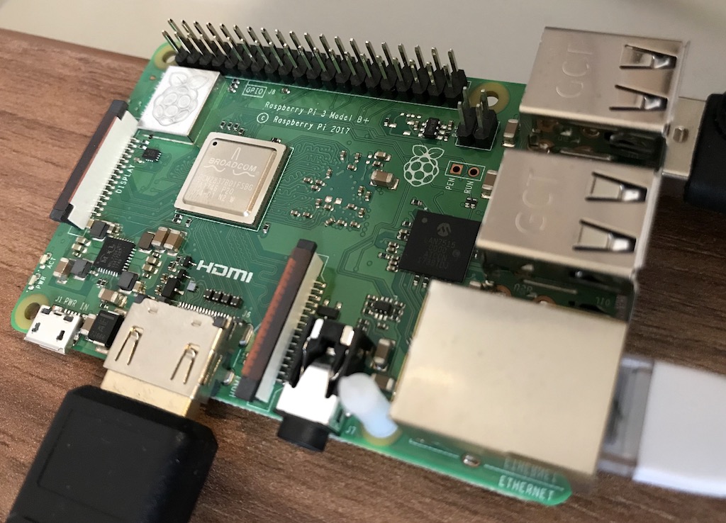
The PowerBlock is an add-on board for the Raspberry Pi (version 1, 2, and 3) models A+ and B+. It provides a microcontroller-based power-switch functionality.
This article describes the PowerBlock itself, as well as how to connect a power switch and how to install the driver.
[box type=”info” align=”aligncenter” class=”” width=”100%”]While this is the original article about the PowerBlock you can find an updated version about the PowerBlock here.[/box]
Functionalities
The PowerBlock provides a power switch functionality. Why might this be of interest for you? The Raspberry Pi comes without a power switch. As soon as you plug the micro USB cable into the RPi, it turns on. If you want to shutdown the Raspberry Pi, you need to call a shutdown command to to bring the system into a state in which you can safely remove the USB cable again. If you just pull out the micro USB cable your file system might become corrupted and you might possibly loose data.
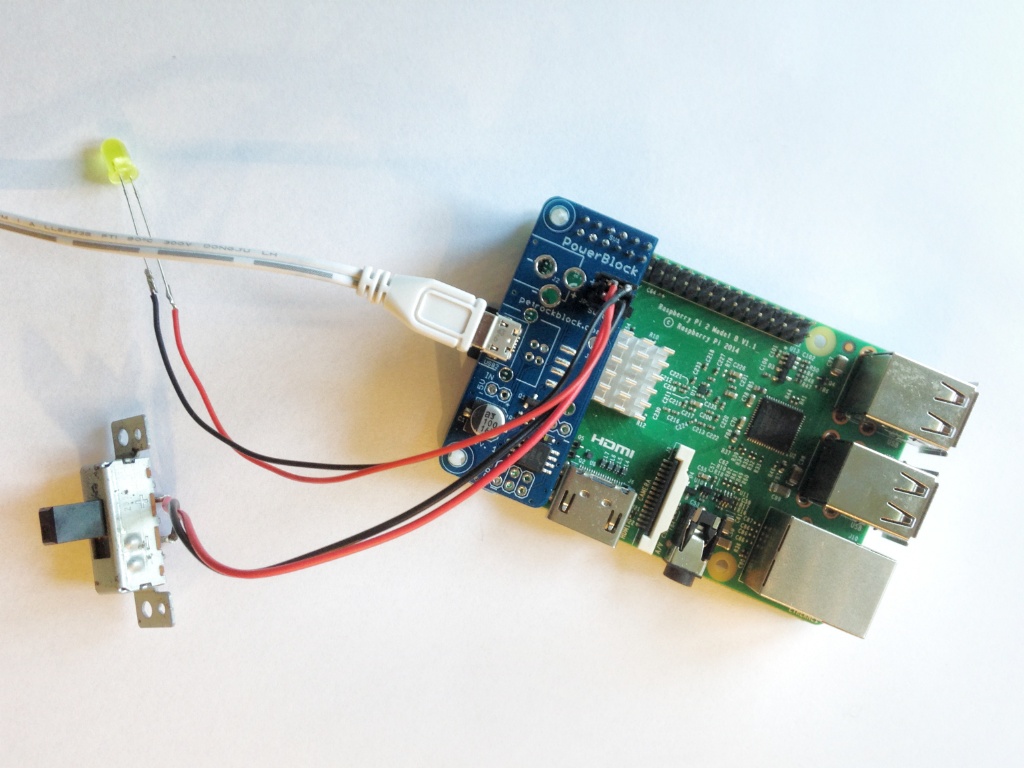
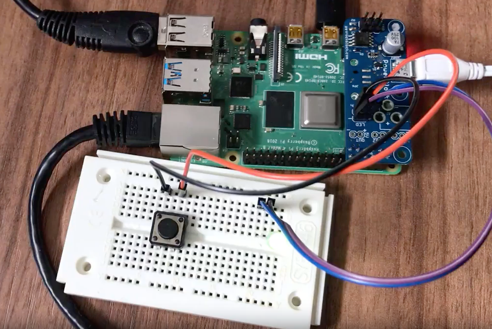
Here, the PowerBlock comes into play. It is stacked onto the GPIO header of the Raspberry Pi and provides a micro USB connector itself, a connector for a toggle switch to control the power supply of the Raspberry Pi, and a connector for an LED to indicate whether the Raspberry Pi is off, booting, running, or shutting down. The power supply is controlled by a tiny microcontroller on the PowerBlock PCB that monitors the button state as well as the state of the Raspberry Pi and switches a MOSFET accordingly. This means that there is no need anymore to plug and unplug the USB cable from the Raspberry if you want to completely and safely turn it off.
Dimensions and Interfaces
Dimensions
The dimensions of the PowerBlock PCB are chosen such that it exactly matches the two mounting holes on the opposite of the USB sockets of the Raspberry Pi models A+ and B+. The PowerBlock PCB comes with the same round corners as the Raspberry itself and give it a neat look. Regarding the GPIO usage the PowerBlock is attached to the first 2×6 pins of the Raspberry Pi GPIO header.
Hardware Interfaces
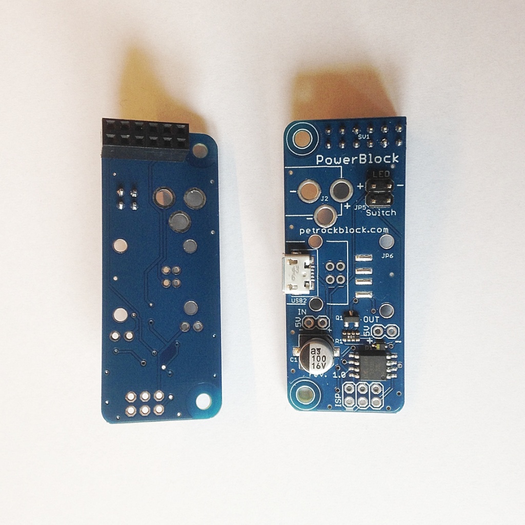
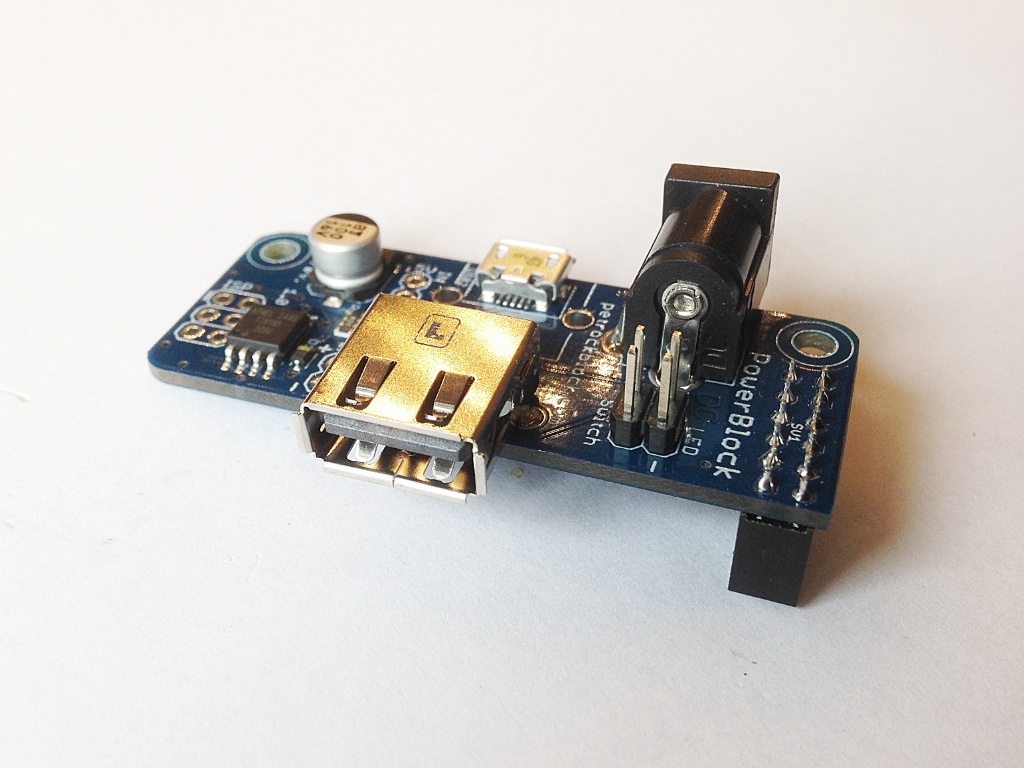
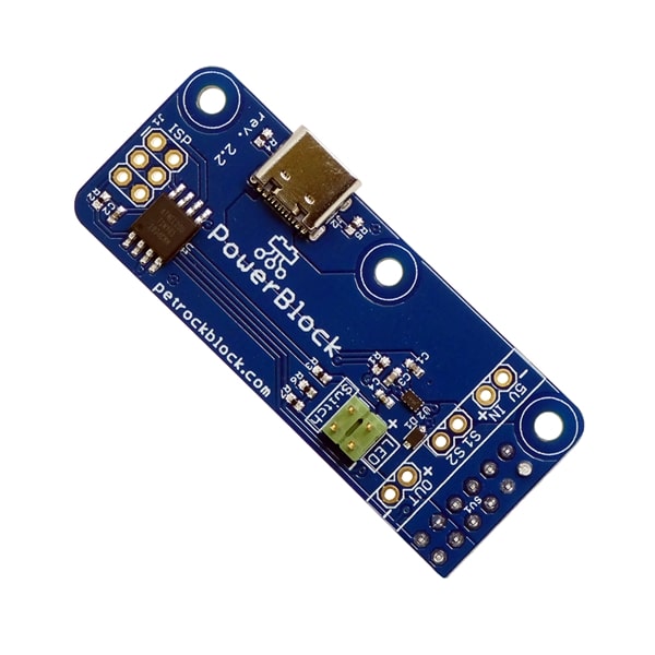
Here are a top and bottom view of the PowerBlock PCB:
PowerBlock Top View
PowerBlock Bottom + Top View
The hardware interfaces of the PowerBlock are described in the following:
2×6 pin female header as connector to the Raspberry Pi
The PowerBlock PCB is attached to the Raspberry with a 2×6 pin female header. This header makes use of pins 1 to 12 of the J8 header. This header is used for connecting the voltage and ground pins as well as the I2C pins between the RPi and the PowerBlock. The PCB is kept as small as possible so that you can easily access all other pins that are not used by the PowerBlock.
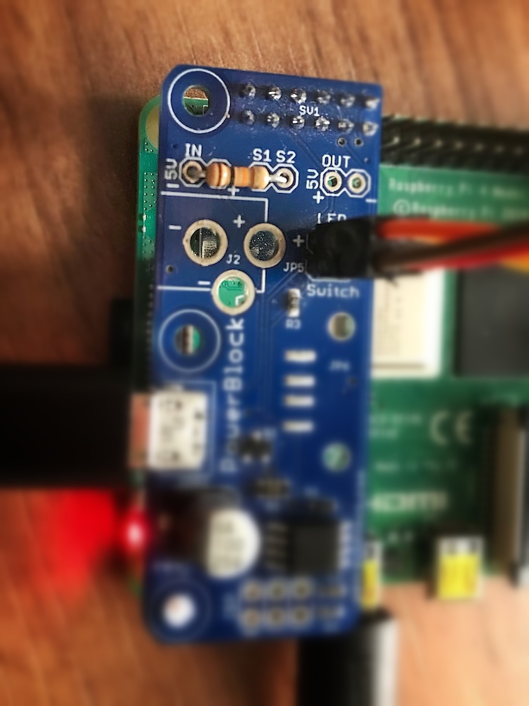
Micro USB Connector for the power supply
The PowerBlock has the same USB Micro connector as the Raspberry Pi. That means you can simply use your existing USB Micro cable for powering the RPi.
Pin Outs for 5V Supply Voltage and Ground
If you do not want to use the USB connector, GND and the 5V supply voltage can also be accessed via two pins so that you could use batteries or whatever you like to power the RPi.
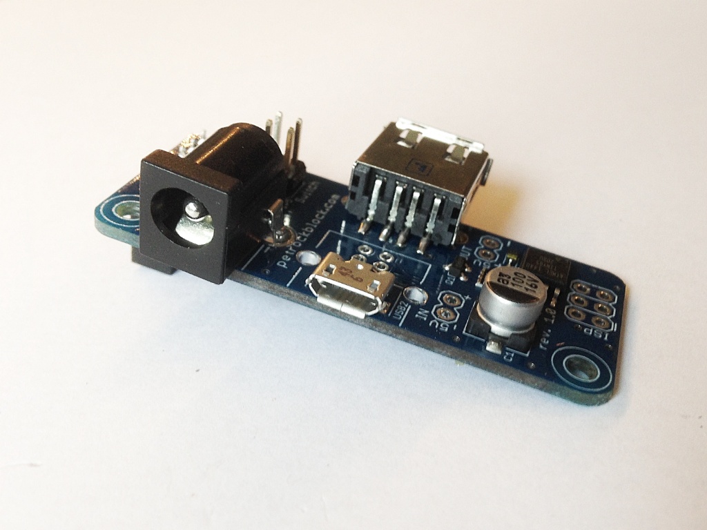
Optional DC Barrel Jack Adapter
The PowerBlock is also prepared for connecting a DC barrel jack adapter. The hole dimensions for the barrel jack adapter are chosen such that most of DC barrel jack adapters should fit. Here is a picture that shows the PowerBlock with the optional DC barrel jack:
Pin Out for a Toggle Switch
To control the power state of the Raspberry Pi the PowerBlock provides an interface for attaching a toggle switch. The on-board microcontroller monitors the state of that switch as well as the one of the Raspberry.
Pin Out for Status LED
The current power state of the Raspberry Pi can be indicated with a 5V status LED that can be attached to the two pins that are provided by the PowerBlock. These states can be “off”, “booting”, “on”, and “shutdown”. The different state are indicated with easy-to-distinguish static and pulsing patterns.
Optional USB A Connector as power out
If you want to provide a switched 5V voltage to another device, you can solder a USB A connector to the PowerBlock – it is prepared for that as well. Here is a picture that shows the PowerBlock with both the optional DC barrel jack as well as the USB A connector:
In-Service Programmer (ISP) pin-out for ATtiny
The Power Switch logic is realized with the help of an Atmel ATtiny85 microcontroller. If you want to you have the possibility to access the microcontroller with the ISP header. In this way you could reprogram the microcontroller with whatever functionality you like.
Assembly of the PowerBlock
Assembly of the PowerBlock? Not needed – it comes fully assembled. You only need to connect a power switch and, optionally, an LED. This is described in more detail in the following.
Attaching a Power Switch
To turn the Raspberry Pi on and off with the PowerBlock you need to attach a toggle switch to the two button pins on the PowerBlock. Technically speaking, the microcontroller on the PowerBlock looks, if the two pins of the switch are connected or not. If they are connected, a GPIO pin of the microcontroller on the PowerBlock is pulled to GND and interpreted accordingly.
[checklist]
It is important that you use a toggle switch and not a momentary button with the PowerBlock. Otherwise the Raspberry Pi will be turned off again right after booting.
If you do not want to use the power switch functionality you can disable this in the configuration file /etc/PowerBlockconfig.cfg by setting “powerswitch”: false.
The power switch circuitry of the PowerBlock leads to a tiny voltage drop and we made the experience that a good quality power supply and a good quality USB cable are mandatory for a working setup. If unsure, we can recommend the official Raspberry Pi Power Supply.
[/checklist]
Attaching a Status LED
The PowerBlock has pin outs for an optional status LED that indicates the power state of the Raspberry Pi. You can directly attach an LED to the pins that are marked with “LED”. You need to pay attention to the polarity of the LED: The LED pins are marked with “+” and “-” for that.
The LED will blink in four different patterns that depend on the power state of the Raspberry Pi:
Off: The LED is simply off.
Booting: The LED slowly fades in and out.
On: The LED constantly stays on.
Shutting down: The LED fades in and out twice as fast as during boot up.
Software Setup and Configuration
The power switch functionality of the PowerBlock is controlled with the GPIO pins 17 and 18 of the Raspberry Pi:
Pin 17 can be used to indicate the power state of the Raspberry Pi. This pin is read by the PowerBlock”s microcontroller to control the on-board power switch.
Pin 18 can be read by the Raspberry Pi to get status of the button that is attached to the PowerBlock.
The PowerBlockService is an open-source driver for the PowerBlock. It provides a service for interacting with the power button signals as well as for mapping attached game controllers to corresponding game pad devices on the Raspberry Pi. The installation only takes a few steps and is done from command line. In the following, this is described in more detail.
Command-Line Installation
The command-line installation consists of these steps:
Installing required packages
Fetching the latest version of the PowerBlock driver and service from the public repository.
Compiling the driver binary.
Installing the driver binary.
Installing the service.
To be able to successfully build the driver you need to have certain APT packages installed:
The following commmands for the command line do the above steps:
[code language=”bash”]
git clone git://github.com/petrockblog/PowerBlock.git
cd PowerBlock
mkdir build && cd build
cmake ..
make
sudo make install
sudo make installservice
[/code]
You might need to reboot your Raspberry in order to have all needed services running.
The above installation procedure is also shown in this video. Please note that, other than in the video, you need to install g++-4.9 as described above:
Video Demonstration
The following video shows the PowerBlock in action:
Cases
What if you want to put your Raspberry Pi together with the PowerBlock into a case? If the RPi together with the PowerBlock fit into your case depends on the lind of power jack and the case you use. Overall, the PowertBlock adds about 6 mm in height to the Raspberry Pi 2 Model B. If you are interested, a user has published his design files for a 3D printable case that fits a PowerBlock at Thingiverse.
Conclusion
The PowerBlock is an extension board for the Raspberry Pi (TM). The key feature of the PowerBlock is a power switch functionality to safely turn on and off the power to the Raspberry Pi with a toggle switch. A connector for a status LED that indicates the power status of the Raspberry Pi can optionally be connected to the PowerBlock.
If you are interested in getting the PowerBlock, you can find it in our shop.
E: Some index files failed to download. They have been ignored, or old ones used instead.
pi@media:~ $ sudo apt-get upgrade -y
Reading package lists… Done
Building dependency tree
Reading state information… Done
Calculating upgrade… The following packages were automatically installed and are no longer required:
pix-icons pix-plym-splash pixel-wallpaper plexmediaserver-installer
Use ‘apt-get autoremove’ to remove them.
Done
The following packages have been kept back:
ghostscript libfreerdp-cache1.1 libfreerdp-client1.1 libfreerdp-core1.1 libfreerdp-gdi1.1 libgs9 libgs9-common python-openssl python3-openssl
0 upgraded, 0 newly installed, 0 to remove and 9 not upgraded.
pi@media:~ $ sudo apt-get install -y git cmake g++-4.9 doxygen
Reading package lists… Done
Building dependency tree
Reading state information… Done
doxygen is already the newest version.
g++-4.9 is already the newest version.
git is already the newest version.
cmake is already the newest version.
The following packages were automatically installed and are no longer required:
pix-icons pix-plym-splash pixel-wallpaper plexmediaserver-installer
Use ‘apt-get autoremove’ to remove them.
0 upgraded, 0 newly installed, 0 to remove and 9 not upgraded.
pi@media:~ $ git clone git://github.com/petrockblog/PowerBlock.git
Cloning into ‘PowerBlock’…
remote: Enumerating objects: 49, done.
remote: Counting objects: 100% (49/49), done.
remote: Compressing objects: 100% (38/38), done.
remote: Total 853 (delta 19), reused 29 (delta 11), pack-reused 804
Receiving objects: 100% (853/853), 2.51 MiB | 1.36 MiB/s, done.
Resolving deltas: 100% (287/287), done.
Checking connectivity… done.
pi@media:~ $ cd PowerBlock
pi@media:~/PowerBlock $ mkdir build && cd build
pi@media:~/PowerBlock/build $ cmake ..
— The C compiler identification is GNU 4.9.2
— The CXX compiler identification is GNU 4.9.2
— Check for working C compiler: /usr/bin/cc
— Check for working C compiler: /usr/bin/cc — works
— Detecting C compiler ABI info
— Detecting C compiler ABI info – done
— Detecting C compile features
— Detecting C compile features – done
— Check for working CXX compiler: /usr/bin/c++
— Check for working CXX compiler: /usr/bin/c++ — works
— Detecting CXX compiler ABI info
— Detecting CXX compiler ABI info – done
— Detecting CXX compile features
— Detecting CXX compile features – done
— JsonCpp Version: 1.7.7
— Found PythonInterp: /usr/bin/python2 (found suitable version “2.7.9”, minimum required is “2.6”)
— Found Doxygen: /usr/bin/doxygen (found version “1.8.8”)
— Configuring done
— Generating done
— Build files have been written to: /home/pi/PowerBlock/build
pi@media:~/PowerBlock/build $ make
Scanning dependencies of target jsoncpp_lib_static
[ 5%] Building CXX object src/lib/jsoncpp/src/lib_json/CMakeFiles/jsoncpp_lib_static.dir/json_reader.cpp.o
[ 11%] Building CXX object src/lib/jsoncpp/src/lib_json/CMakeFiles/jsoncpp_lib_static.dir/json_value.cpp.o
/home/pi/PowerBlock/src/lib/jsoncpp/src/lib_json/json_value.cpp: In constructor ‘Json::Value::Value(Json::ValueType)’:
/home/pi/PowerBlock/src/lib/jsoncpp/src/lib_json/json_value.cpp:346:27: warning: declaration of ‘empty’ shadows a member of ‘this’ [-Wshadow]
static char const empty[] = “”;
^
[ 17%] Building CXX object src/lib/jsoncpp/src/lib_json/CMakeFiles/jsoncpp_lib_static.dir/json_writer.cpp.o
[ 23%] Linking CXX static library libjsoncpp.a
[ 23%] Built target jsoncpp_lib_static
Scanning dependencies of target powerblock-app
[ 29%] Building CXX object src/powerblock/CMakeFiles/powerblock-app.dir/PowerBlock.cpp.o
/home/pi/PowerBlock/src/powerblock/PowerBlock.cpp:24:22: fatal error: plog/Log.h: No such file or directory
#include
^
compilation terminated.
src/powerblock/CMakeFiles/powerblock-app.dir/build.make:62: recipe for target ‘src/powerblock/CMakeFiles/powerblock-app.dir/PowerBlock.cpp.o’ failed
make[2]: *** [src/powerblock/CMakeFiles/powerblock-app.dir/PowerBlock.cpp.o] Error 1
CMakeFiles/Makefile2:514: recipe for target ‘src/powerblock/CMakeFiles/powerblock-app.dir/all’ failed
make[1]: *** [src/powerblock/CMakeFiles/powerblock-app.dir/all] Error 2
Makefile:127: recipe for target ‘all’ failed
make: *** [all] Error 2
I did finally manage to get this to build on my wheezy based pi, but it was a super pain to do because wheezy only goes to g++-4.8 I spent a long time fighting with it.
to get the parts from a jessie build and then manually did the cmake setup with -DCMAKE_C_COMPILER= and -DCMAKE_CXX_COMPILER= definitions on the cmake command line pointing to the new 4.9 stuff. Just exporting CC and CXX in the env didn’t work for me.
Hopefully this will help other’s trying to get PowerBlock working on a wheezy pi.
You mention customization of the program running on the ATMEL chip by connecting through the ISP header. Is the default program contained on the ATTINY chip located on your github? I can’t seem to find it.
I’ve just received the power block and am building a custom case for my setup. Since the power block takes up the necessary GPIO pins for running a small fan, is there an alternative way to power a small cooling fan?
The PowerBlock has 5V output pins (+, -). These pins are also switched by the PowerBlock. As long as the fan does not draw too much current, those pins could be used. The maximum current the PowerBlock can handle is 3.7 A – including the current consumption of the Raspberry! If you need more power you could use the output pins to switch, e.g., a relay. Hope that helps!
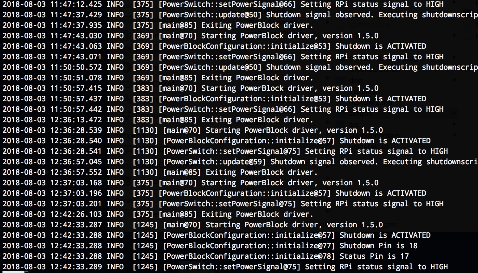
Hi! So is the git software used to execute the shutdown command? Is it possible to execute a python script once shutdown is initiated? I’d like to turn power on off for an arduino when the pi shuts off?
i installed the PowerBlock and everything seemed to go well.
i switched on the Pi and the LED flashed while booting into Retropie.
Retropie loaded up but the LED continued to flash I pressed the switch to powerdonw but nothing happened the LED just continued to flash.
Any ideas on how I can resolve this?
Hi! If the LED keeps flashing it means that the PowerBlock driver is not running properly. It would help if you could post the output of the driver and service installation.
Hi. I tried everything to get it working but it refused to do so. I then tried it on another Pi with the same SD card and it worked fine! This is strange as the Pi is fine and has been running Retropie with no issues.
Any ideas as I have ordered another PowerBlock?
Then it would help if you could post the output of the driver and service installation.
Erkan says:
I will try but it might not be possible.
edgecuted says:
Hello everybody, a friend and I are working on a Raspberry pi3 model B in a Megadrive 2 case. We bought a Powerblock to be able to use the original powerswitch button and the original LED. When trying to install all the PowerBlock stuff, we ran into errors such as :
pi@retropie:~ $ git clone git://github.com/petrockblog/PowerBlock.git
fatal: destination path ‘PowerBlock’ already exists and is not an empty directory.
pi@retropie:~ $ cd PowerBlock
pi@retropie:~/PowerBlock $ mkdir build && cd build
mkdir: cannot create directory ‘build’: File exists
pi@retropie:~/PowerBlock $ cmake ..
CMake Error: The source directory “/home/pi” does not appear to contain CMakeLists.txt.
Specify –help for usage, or press the help button on the CMake GUI.
pi@retropie:~/PowerBlock $ make
make: *** No targets specified and no makefile found. Stop.
pi@retropie:~/PowerBlock $ make ..
make: Nothing to be done for ‘..’.
We still get the cmakelists error after installing the drivers again. Any idea on how to solve this ?
Oh, and the LED keeps on blinking when the Raspberry is on.
I just received my PowerBlock, wired it up, installed the driver and it’s working except that it never actually cuts power to the Raspberry Pi and stays blinking after shutdown. What am I doing wrong?
Hi, hope ok to post a query here. I have a raspberry pi 3, latest official retropie, plus a powerblock. I have a switch wired in I beleive is latching (Maplin: http://www.maplin.co.uk/p/illuminated-red-push-to-make-switch-n07ar ) and the power connected to the powerblock.
i’ve found a couple references to a similar issue where if I use the switch to power off, the machine shutsdown neatly then instantly powers back up again even tho the switch is now “open”.
the machine will not cold boot when the switch is open!
have I just wired the switch up to the wrong pins, or have the wrong type of switch! I’m not using the LED side of the switch, just the 2 pins to the 2 pins on the switch.
thank you for your help, it seems an ideal solution but user error? :)
You can check, if the PowerBlock works properly by connecting the switch pins directly with each other (without any button in between). If they are connected the PowerBlock should turn on the RPi. As soon as the are disconnected a shutdown signal should be triggered.
hi, ok I tried that and it works perfectly. then I switched my weak little brain on and … I described this completely insanely wrongly.
The actual situation is this:
Now I have the powerswitch driver installed, the switch works as expected.
BUT if i now shut down the pi from the emulationstation quit menu option, the pi shuts down and starts up again on its own. it didnt do this before i installed the driver.
thats the issue. sorry for confusing matters with a bogus report.
That is because the PowerBlock/ControlBlock only looks at the status of the attached switch. You should use the switch only to switch of the RPi.
iain hancock says:
Hello
coming back to this if you dont mind. so with the powerblock driver installed, i can – these are as my current experience –
1. I can only switch the pi off by using the power switch attached to the pi3, Yes?
2. from command line on the pi, ‘sudo shutdown now’ – the pi will shut down and stay off. Yes?
3. but choosing the ‘shutdown’ option from emulation station/under retropie will not work. the device will reboot because the power switch is closed. yes?
is there a workaround for case 3?
thank you! iain :)
KiwiBri says:
hi, did you get answers to this?
iain hancock says:
no reply.
I’m still hoping the powerswitch and driver does not stop me turning off the system from ES. It seems odd to kill that functionality. Thats why I think i have something set up badly, that cant be right. why would it break or change that?
i can still ssh into the pi, sudo shutdown now, that works, but the powrswitch seems to have stopped the ES menu option from working.
There is no workaround for case 3 – the hardware switch overrules the software in this case.
Rémi says:
Hello,
Can you tell me which pins are really used by the powerblock ? I would like to know if some of them are free to use them with an other software.
I also see a “5V + – IN” inscription on the board, may I use this for the power supply instead of the micro usb port ?
Thank you !
Oh, I’ve missed this page, thanks for the informations and the quick reply !
Jason Pereira says:
Hi there,
I wanted to add an extra switch to the powerblock so that I could invoke an umount script to un mount the usb drive where my roms are stored. Can I use pins 11/12? it seems from the pi3 GPIO header pins 11/12 are GPIO17 & GPIO18, so by reading those pins I should be able to detect a button press(connect to ground). Are my assumptions correct?
Where in the software do you change the pins being used?
Lodmot says:
Hey there.
I got a PowerBlock for my project where I’m installing the Raspberry Pi in an old Sega Genesis Model 2 shell. I plugged the power supply (made for use with Raspberry Pi 3) into the micro USB port on the PowerBlock itself, and I am using the original toggle power button from the Sega Genesis motherboard. I’m pretty sure the power button and the LED is properly connected, but when I press the power button, absolutely nothing happens. So do I need to configure the software first before this device will physically work, or should I already have been able to turn it on even without the software installed?
Nevermind, I figured it out! Turns out I had the switch connected wrong (the power switch in the Sega Genesis model 2 has 5 pinouts, I apparently was using the wrong combination). Works really awesome! Thanks! :D
I have a PI, also have an Ouya with a 1 terabyte all games, not bad, Run Kodi on both too.
Which Reminds me of when I was a test patient for Viagra but Left because everyone was pretty Hard-On me.
Seems I can’t keep a job, I worked at a sperm bank but was let go due to Carpal Tunnel :(
Lodmot says:
Lol! xDD But yeah, you should see this console I’m putting together. It’s still a work in progress, but it’s pretty sweet! ^^
Hans Olo says:
Keep me posted I like making my own retro consoles, got thousands on mine.
1 terabyte of games on Ouya? XD Is that like 100 Angry Birds clones + a few Farmville clones or what? Is this the entire Android Play Market on an SD card or something? And is any of that actually enjoyable to play?
Are the drivers compatable with Fedora 25? I have one SD card loaded with every NOOBs OS to try them out and learn them and another I am loading with Fedora 25.
Hi, I am interested in getting the powerblock as I will be installing it into a cabinet with the pi. I’m not too familiar with with electrical components but I’m trying to find out how the LED wires and the toggle switch wires are connected to the pins? It looks like most pictures online show some sort of black connectors which I can find on multiple sites but what size are those pins so that i can find the right size connector? I’m not referring to the GPIO pins but instead to the pins that the LED and toggle switch connect to. I’m trying to gather and purchase all the pieces at once so I don’t have it in front of me to measure. Thanks for making the power situation easier!
Hi I have the powerblock installed and working but what I am trying to do without success is get the Rasoberry Pi to autimatically run a script so that I do not need to have a mouse or keyboard attached.
Storenvy, the host of our shop, seem to have server issues right now: http://status.storenvy.com. Maybe another DDoS attack?
Sorry for any inconveniences!
could work with powerblock ( either light + power on/off together ) ?
Another question.
I have totally no idea what cable and connector should i use to connect this type of button to the powerblock.
what kind of cable should i buy ( look at the image )?
I dont know either the name of the connectors of the switch either the connector of the power block. Is there a cable “pre-made” that suites it?
Have you maybe some Amazon’s link for that?
thanks for your reply!
Should i connect to this button all 4 connectors of the power block ( 2 for the switch and 2 for the led ) or maybe i have to connect only the two switch connector?
The two pins near the text “switch” are + and – for the switch pins. The two pins near the text “LED” are + and – for the LED. You might find further details about the switch in the data sheet of the switch.
could work with powerblock ( either light + power on/off together ) ?
Another question.
I have totally no idea what cable and connector should i use to connect this type of switch to the powerblock.
what kind of cable should i buy ( look at the image )?
I dont know either the name of the connector of the switch either the connector of the power block. Is there a cable “pre-made ì” that suites it?
Have you maybe some Amazon’s link for that?
could work with powerblock ( either light + power on / off together ) ?
Another question.
I have totally no idea what cable should i use to connect this kind of switch to the powerblock
what kind of cable should i buy ( look at the image )?
I dont know either the name of the connector of the switch either the connector of the power block. Is there a cable that suites it?
Have you maybe some Amazon’s link for that?
If I use a rocker switch with a built-in LED (as Vman41 mentioned a while back) that has only 3 connectors: +, GND, A (as in http://max.import.free.fr/Doc/Schema/inter_temoin2.gif) can I simply connect the GND of the button to any one (or both) of the LED- or SWITCH- pins of the PowerBlock? They both seem to be ground, right? Thanks!
I just got mine last night and i set it up with no problem. I would recommend you to reboot the rpi before the second set of codes. Same morning I went to Fry’s electronics and the guy was not helpful at all like “don’t ask me anything dude!”. I tried to pick the right wires, button and light and luckily they all worked perfect.
PowerBlock was working great! Then I transferred it to a new Raspberry Pi with latest RetroPie and all of the PowerBlock software installed.
Now, PowerBlock gracefully shuts down the Pi, but won’t start it back up?
Any ideas?
I would like to power a usb3 hdd from the powerblock along with my pi3. The drive is rated at 5V 1A. I am using a 5V 3.8A power supply. Assuming that the pi and hdd don’t draw too much for the mosfet, can I split a usb cable and solder the power and ground directly to the powerblock? Or should I attach a USB A connector and buy a “y” cable? I see 4 pads for the USB A connector, but I am assuming it only uses +5V and ground. Is their an advantage or disadvantage to either way? I’m trying to avoid a powered usb hub since this is the only usb device I need. If I can power and switch both from the powerblock, that would be great.
You can solder a USB-A connector to the PowerBlock – it already provides the mounting/solder pads for that connector. The USB-A connector is connected to the switched supply voltage. The MOSFET on the PowerBlock is rated for 3.7 A, so it could work. Unfortunately, I cannot give you a definitive statement. I guess you need to try it out with your hardware setup. Does this help?
Mine is on the way! I’m looking to wire up the switch and LED, what is the connection to the pcb called, or does the powerblock come with it? Also, if I’m connecting to a SPST switch with a built in 5v LED, would I just combine the “-” at the PCB or switch, and run three lines to the swtich (switch on, led + and common). Sorry if it’s a silly question, just want to get it right.
The default connector is given as two pins with a 0.1″ spacing. You should connect the “out 5V +/-” pins to the LED, because the other pin might not provide the needed current.
Can you give me the measurements for the location of the micro usb port on this(when it’s connected to a raspberry pi 3)? I’m almost done designing a laser cut retropie box to accommodate this and a latching push button.
I have not measured it myself so far. However, you might find these measurements and get some ideas at http://www.thingiverse.com/thing:1077472.
Hope that helps!
I have another question this time in regards to the LED output. Would it provide enough voltage to driver say a small EL panel (10mm x 10mm) through a 3v inverter rather than just an LED or would I have to go the optional USB connector route?
The maximum current of the LED output is 40mA. I did not look into the technical data sheets, but I am pretty sure that the EL panel does not work with that constraint.
The + and – go to the LED pos and neg on the Power Block. The only thing that differed is that this diagram is for a normally closed setup and I wanted the switch to be normally open(so when I clicked the button in, the pi turns on). So instead of using the top left and right plugs, I used the middle and right. And those went to the two switch headers on the Power Block.
Hey PetRock, I’m wishing to use this in an arcade cabinet, and love how one switch is able to safely shut down my Pi! My question is, if I am able to use a DPST switch controlling the pi on one pole, and the other circuits ie. TV, speakers etc, on the other pole, but powered by the same socket supply with a power-off delay board introduced to compensate for the shutdown time, would this work safely?
Do you think I am able to use a dpdt switch of the off on on arrangement to control the powerblock’s switch control, then use the micro usb as the power, or would that fry the board?
Joeseph Espinosa says:
Very novice question here, but I plan on on using this board but I do not wish to directly mount it on top of the Pi, could I somehow unsolder the gpio pin connector and then solder in some headers? What is the best way to do accomplish this? I will be mounting the powerblock on a bracket in such a way that the connector will be in the way, so I will at the very least need to remove it and place it on top for this reason alone.
Just ordered one and I’m wondering if you think this switch will work as both the switch and indicator led. It’s 4 pin and the light is supposed to be seperate from the swithc, I assume it’s LED but they don’t actually say.
That type of switch works wit the PowerBlock. There is just not much information about the required LED voltage for the switch. But I would bet that it also works with the PowerBlock. It would be great, if you could post your experience with that switch here or in the forum at https://retropie.org.uk/forum/category/14/controlblock-powerblock-co.
Just wanted to say that the PowerBlock worked out perfectly for my undergraduate engineering senior design project: a Raspberry Pi-based control system for an indoor pistol range. The system times NRA Bullseye pistol tournament rounds, plays audio files in sequence for the rangemaster commands, and automatically rotates the targets facing or away from the shooters at the appropriate times by interfacing with a compressed air system using solid-state relays.
We needed a way to power the entire system on and off with a single toggle switch while allowing our Raspberry Pi to boot up and shut down gracefully, and the PowerBlock was the solution! Thanks for the great design and documentation.
I’m just starting learing about the raspberry pi and I have a quick question. Rather than using a separate LED indicator, would it be possible to wire it to a rocker switch that has a built-in LED? That way you have both the switch and LED in one component. Something like this: https://www.sparkfun.com/products/11155
Thanks! Also, just to be clear… it’s still possible to get the blinking to happen with this type of setup? Like I said, I’m very new to this.
John Smith says:
Are there any other “compatible” cases for the RPi3 and the PowerBlock? I’d rather purchase one than to try get the 3D printer files made somewhere. Unless there’s an easy way to order a print off of Thingverse.
You mean a 6amp power supply? That would work! It is important not to have a supply voltage of 5V. The drawn current depends on the attached devices, which would work with the Raspberry and the PowerBlock.
I’ve just installed my powerblock and am having a problem where immediately after startup my device will reboot as if I am using a momentary switch. I have tested that it is not my wiring that is the problem, and I directly copied the the command line code for installing the switch software. Do you have any suggestions for searching the for the problem or avoiding the software turning the pi off immediately after startup so that I can attempt to reinstall the software? Thanks!
The implemented logic on the PowerBlock expects the switching behavior of a toggle (i.e., non-momentary) switch: As soon as the state machine is in the “ON” state and observes a low signal level on the switch pin, it initiates the shutdown. See also the issue at Github https://github.com/petrockblog/PowerBlock/issues/1#issuecomment-197732252.
When i try to turn on my rpi using the powerblock, the LED indicator stays flashing even when the rpi is on all the way. Upon switching the powerblock off, the rpi stays on. Could I have messed up the powerblock or is this just a ‘simple’ software issue? I’m running retropi on wheezy right now so I can’t update the powerblock script. but up until this point it has been running fine.
If the LED stays flashing after boot it means that the PowerBlock micro controller does not get the status pin signal as feedback from the Raspberry. I guess it is “only” a software issue, i.e., the PowerBlock driver is not installed / running correctly. I would try and re-install the driver as described in Section “Command-Line installation” at https://www.petrockblock.com/2015/07/04/powerblock-another-power-switch-for-the-raspberry-pi/. Hope that helps!
The only issue I had with reinstalling is that when I run sudo make install it says I don’t have G++4.9. I am running on wheezy(and for other reasons cannot upgrade to Jessie by reflashing), so I can only have version 4.8. Is there anyway to reinstall with only having version 4.8?
Witsawut says:
hi
I have the same problem as you.Please tell me how can I fix it?
Caleb Schnell says:
It turns out that it was my RPI that was messed up. Do you have another that you can test? I would also try reflashing the SD card to mark that out as a possibility.
Witsawut says:
I have only one RPI. How do you solve a problem Edit2 in your post?
Caleb Schnell says:
Oh yeah, find the powerblock installation file that says G++-4.9 and change it o 4.8. I can’t remember whicj file it is, but it’s all in the folder that you download to install powerblock.
Witsawut says:
Thank so much.Now I can fix it. :)
Caleb Schnell says:
Yeah I don’t know what is wrong with it. I reformatted my SD card with the latest version of Retropie and even then it won’t work. Upon flicking the switch, the light goes right to solid light beforwe it’s booted up all the way. I can’t think of what I might have messed up for it to not work like this.Any ideas are appreciated
Maybe you can post an image with all your wiring here?
Caleb Schnell says:
And I feel like an idiot. It works on a different RPI2 with the same SD card. I’m 99% confident it’s the rpi, I must have burnt something out or messed up a pin somehow. Gotta be careful when the power is sent through the GPIO pins in the pi.
Thanks for your help and excuse my ineptness, haha.
Might be. Does it work, if you try to install g++-4.8? sudo apt-get install -y cmake g++-4.8
Lino Ricardo Lopes says:
Hi guys. I have a question: I have a broken (kids) tablet, and i was thinking about keeping the battery to power my py2. The battery has 3 wires. The powerblock manage to be powered by battery, and recharge when plugged on usb? Do you have a simple schema to show how to plug it?
i would not try to charge the battery with the powerblock. Lithium Ion batteries are ‘delicate’ which means they can be undercharged and killed, and overcharged and can catch fire. You’ll want to get a lithium ion charging circuit that can both charge and discharge the battery. You’ll then solder the discharge part to the powerblock input. That way the battery has some form of protection on it. And you’d probably also need something to keep the voltage at a constant 5v. I can’t imagine the Rpi likes to be running at 3-4.1v all the time.
Hello. Just a question. I want to try recalbox to compare with retropie. Does the powerblock works with recall? (I am a noob… ) if yes, is it enough to follow the tutorial? Or it need to be installed differently?
Thanks for your answer. I try just before, but I am not sure recalbox is based on raspbian. I try to send the commands but none worked. Even (sudo) apt get. I saw there is more persons asking the same on some posts but none get an answer.
The problem I have with retropie (except pifba and snes remote) is my screen. It’s a 1024×600 screen, and i wold like to use full screen. But everytime I try to go up than 640×480, I have those black borders. I tryed several posts and tutorials, but nothing…
cayman says:
The PowerBlock looks good! Can it be used with a momentary button? Thank you
I have a raspberry pi 2 and a control block and I am looking for a case that can house them does anyone know of a case that will work with no modification?
Can this be used on a Arduino Uno or Mega and provide the same concept? Also, can you hook up a raspberry Pi and Arduino together on one connection? What would be the maximum amps the power block can provide?
The MOSFET is rated for maximum 3.7 A. The PowerBlock uses two signal lines to get status information from the Raspberry Pi. These signals are provided by the PowerBlock driver mentioned above. In principal, this concept could be adapted to an Arduino as well. But I am not aware of an Arduino driver, though.
Thank you for the response. I have a project that will require an Raspberry Pi to work together and want to use the power block. This why I am asking if the power block can work for both of them. It sounds like it won’t based on the driver for the Arduino. Couldn’t the out power be placed to the Arduino power in and controlled that way?
Also, I will end up placing my switch a distance from the Raspberry Pi and my require a larger wire than normal based on Voltage drop. Will the switch still work if it wired to a terminal block and then to the power block.
Hi Florian.
My PowerBlock is coming, and I would like to add a very simple command that let the PI send a mail before switching off.
Up to now I have used mutt just before shutdown in a python script that intercepts GPIO’s events.
Where and what can I change in PowerBlock configuration to add a feature like that?
Thanks a lot,
If you do not want to or cannot use the Micro USB plug of the PowerBlock, you can alternatively use the “5V IN” pins or a DC barrel jack adapter (that might not be an option in your case). Take care for the polarity in any case. Especially the 5V IN pins can be connected to any suitable power source.
Hello, This looks great, I think I’m going to have to buy one.
Is there any risk of damaging the Raspberry pi using it though? I’ve read that powering through the GPIO connector bypasses the power protection on the Pi itself and can in some cases result in the Pi being fried. Does the PowerBlock itself have any built in protection to help prevent this happening?
The PowerBlock (as well as the ControlBlock) provides an over-voltage spike protection. Also there is a decoupling capacitor to stabilize the supply voltage. The PowerBlock does not provide a fuse, though. That is to keep the voltage drop of the power switch (mainly at the MOSFET) as small as possible. Since the release of the PowerBlock I have not had any problems with the PowerBlock nor have I heard from others that it damaged their RPi. I hope that helps?
You can find the sources at https://github.com/petrockblog/ATTinyPlusPlus. I would be very glad, if you would submit a pull request or similar when you done to further enhance the code :-)
Thanks, I will have a look. It seem’s quite easy to detect an edge instead of the level (with the ability to detect “long press” to do a hard power off”
Could you send me also the schematic?
Daniel says:
Hey there guys,
I just recieved my powerblock a few days ago, but…
I’d rather want a momentary button aswell(with the long press for power off). Any progress on the code Guillaume?
I’d want the schematics aswell, power block is slightly too big original, thinking about making a smaller custom one.
Thanks in advance,
/Daniel
Joshua Kraling says:
After soldering the barrel connector and USB A connector, I plugged the PowerBlock into my Pi. I’m using a 5V 2A power adapter. I plugged it in, and nothing happened. The Pi won’t power up. What am I doing wrong?
– Only connect the power supply to the PowerBlock (and nothing to the RPi directly). If you do not want to use the power switch functionality, see below.
– If you only want to use the terminal blocks for connecting controllers and do not want to have the power switch functionality, you must connect the power supply directly to the RPi.
– Use a toggle switch and not a momentary button.
– In case of the barrel jack connector make sure that you are using the correct polarization.
I found the problem. It’s helpful if the wiring I’m using is good, and doesn’t have a break. I swapped out the power switch wiring and everything works great. Excellent product!!
Marina Maryna says:
Many thanks for this post! Great job! It works like a clock)
I have been used Raspberry Pi for a long time and also have one more question for you. I decided to set up the aux switch for it and even buy one, it was something like this http://hardware.nl/hulpschakelaar/siemens and then I found article that I can make it by myself. It shows how to make it at least I need only 37 $ and I wanna try it. Did you do something similar to it?
Nevermind… Already tested and works perfectly. Is a very effective and enjoyable device. Now, if you don’t mind, I have another question:
What are the exact pins the switch uses? e.g, can I use the UART pins (8+10) for other purposes, or they are actually used by the device?
Many thanks
The PowerBlock uses pins 11 + 12 as control lines.
Fernando Jorge says:
Thank you for your answer.
In fact, this little device is so useful that soon any raspberry becomes meaningless without it. It’s really a must have.
Eric Lacomblez says:
Hi,
sorry long post..
I’d like to use this switch on my current media center projet (osmc/kodi).
The goal is to embed all the stuff into one “hi-fi” looking box and having only 1 power switch to deal with Rpi and **drives**.
By ‘all the stuff’ I mean 1 Rpi2, attached to an external Kb plus an external mouse and a wifi usb dongle (that’s all that is powered by the Rpi itself),
and one powered usb hub attached to one 1TB hdd plus an usb bluray drive.
I won’t use any more the two 5V/2A power supply (the one delivered with the Rpi and the one coming with the hub) but a unique 5V/4A power suply.
So… I guess if I use a unique current circuitry branch, the powerBlock won’t handle such current value ?
I presume I can wire 2 branches from the power supply, that would logically dispatch 2A each (or something). ?
In this last case, nothing will switch off the drives part, and that’s a pain.
is there an instantly available 5V output on the PowerBlock, that could be use to drive a relay that will switch off/on the usb hub circuitryfor hdd, and BR ?
(this means, **as soon** as the Rpi is starting to boot the relay must connect and it can’t wait the Rpi to be booted, otherwise the Hdd won’t be mounted).
I have a PowerBlock which works great, thanks, but I’d like to use the attachment for the USB A connector to run a powered USB hub. Would it be suitable for this? The Pi2 doesn’t give out enough juice to run the two USB sticks, bluetooth adapter and wireless mouse+keyboard adapter that I need to attach.
I’m a little rusty on my electronics – if I powered a hub from the PowerBlock, would I need a more powerful PSU than the one I’m currently using (1.8A, recommended for the Pi2), or would it give sufficient current to the hub as well as the current it already provides to the Pi?
The MOSFET on the PowerBlock is specified with a maximum current of 3.7 A. What kind of power supply you need depends on the device that you want to attach to the RPi. You could start with you existing power supply and if that does not work reliable you can further dig into that.
I think so – it sounds like I can definitely use the PowerBlock to power the USB hub, it might just mean I need a new power supply, which is totally doable. I can’t imagine all those devices together taking up more than 3.7A.
Blue says:
What is the maximum current I can provide to the PowerBlock via the Barrel Jack input? Could I, for example, use this ( https://www.pololu.com/product/1462 ) 5V/5A power adapter?
The MOSFET is a IRLML6402, so I would say that you should make sure that, say, the current does not become more than about 2-2,5A, otherwise the MOSFET would probably fail. The 3A version from Pololu should probably also works well.
 ControlBlock
1 × $ 31.85
ControlBlock
1 × $ 31.85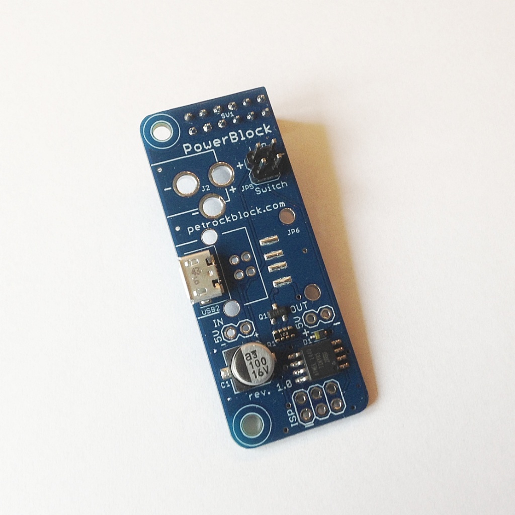


Hi, having issues installing:
pi@media:~ $ sudo apt-get update
Hit http://archive.raspberrypi.org jessie InRelease
Hit http://mirrordirector.raspbian.org jessie InRelease
Get:1 https://dev2day.de jessie InRelease [301 B]
Ign https://dev2day.de jessie InRelease
Get:2 https://dev2day.de jessie Release.gpg [303 B]
Ign https://dev2day.de jessie Release.gpg
Get:3 https://dev2day.de jessie Release [299 B]
Ign https://dev2day.de jessie Release
Get:4 https://dev2day.de jessie/main armhf Packages [322 B]
Hit http://archive.raspberrypi.org jessie/main armhf Packages
Get:5 https://dev2day.de jessie/main Translation-en_GB [323 B]
Hit http://archive.raspberrypi.org jessie/ui armhf Packages
Get:6 https://dev2day.de jessie/main Translation-en [320 B]
Get:7 https://dev2day.de jessie/main armhf Packages [322 B]
Get:8 https://dev2day.de jessie/main Translation-en_GB [323 B]
Get:9 https://dev2day.de jessie/main Translation-en [320 B]
Get:10 https://dev2day.de jessie/main armhf Packages [322 B]
Get:11 https://dev2day.de jessie/main Translation-en_GB [323 B]
Get:12 https://dev2day.de jessie/main Translation-en [320 B]
Get:13 https://dev2day.de jessie/main armhf Packages [322 B]
Get:14 https://dev2day.de jessie/main Translation-en_GB [323 B]
Get:15 https://dev2day.de jessie/main Translation-en [320 B]
Get:16 https://dev2day.de jessie/main armhf Packages [322 B]
Err https://dev2day.de jessie/main armhf Packages
HttpError404
Hit http://mirrordirector.raspbian.org jessie/main armhf Packages
Get:17 https://dev2day.de jessie/main Translation-en_GB [323 B]
Ign https://dev2day.de jessie/main Translation-en_GB
Hit http://mirrordirector.raspbian.org jessie/contrib armhf Packages
Get:18 https://dev2day.de jessie/main Translation-en [320 B]
Ign https://dev2day.de jessie/main Translation-en
Hit http://mirrordirector.raspbian.org jessie/non-free armhf Packages
Hit http://mirrordirector.raspbian.org jessie/rpi armhf Packages
Ign http://archive.raspberrypi.org jessie/main Translation-en_GB
Ign http://archive.raspberrypi.org jessie/main Translation-en
Ign http://archive.raspberrypi.org jessie/ui Translation-en_GB
Ign http://archive.raspberrypi.org jessie/ui Translation-en
Ign http://mirrordirector.raspbian.org jessie/contrib Translation-en_GB
Ign http://mirrordirector.raspbian.org jessie/contrib Translation-en
Ign http://mirrordirector.raspbian.org jessie/main Translation-en_GB
Ign http://mirrordirector.raspbian.org jessie/main Translation-en
Ign http://mirrordirector.raspbian.org jessie/non-free Translation-en_GB
Ign http://mirrordirector.raspbian.org jessie/non-free Translation-en
Ign http://mirrordirector.raspbian.org jessie/rpi Translation-en_GB
Ign http://mirrordirector.raspbian.org jessie/rpi Translation-en
W: Failed to fetch https://dev2day.de/pms/dists/jessie/main/binary-armhf/Packages HttpError404
E: Some index files failed to download. They have been ignored, or old ones used instead.
pi@media:~ $ sudo apt-get upgrade -y
Reading package lists… Done
Building dependency tree
Reading state information… Done
Calculating upgrade… The following packages were automatically installed and are no longer required:
pix-icons pix-plym-splash pixel-wallpaper plexmediaserver-installer
Use ‘apt-get autoremove’ to remove them.
Done
The following packages have been kept back:
ghostscript libfreerdp-cache1.1 libfreerdp-client1.1 libfreerdp-core1.1 libfreerdp-gdi1.1 libgs9 libgs9-common python-openssl python3-openssl
0 upgraded, 0 newly installed, 0 to remove and 9 not upgraded.
pi@media:~ $ sudo apt-get install -y git cmake g++-4.9 doxygen
Reading package lists… Done
Building dependency tree
Reading state information… Done
doxygen is already the newest version.
g++-4.9 is already the newest version.
git is already the newest version.
cmake is already the newest version.
The following packages were automatically installed and are no longer required:
pix-icons pix-plym-splash pixel-wallpaper plexmediaserver-installer
Use ‘apt-get autoremove’ to remove them.
0 upgraded, 0 newly installed, 0 to remove and 9 not upgraded.
pi@media:~ $ git clone git://github.com/petrockblog/PowerBlock.git
Cloning into ‘PowerBlock’…
remote: Enumerating objects: 49, done.
remote: Counting objects: 100% (49/49), done.
remote: Compressing objects: 100% (38/38), done.
remote: Total 853 (delta 19), reused 29 (delta 11), pack-reused 804
Receiving objects: 100% (853/853), 2.51 MiB | 1.36 MiB/s, done.
Resolving deltas: 100% (287/287), done.
Checking connectivity… done.
pi@media:~ $ cd PowerBlock
pi@media:~/PowerBlock $ mkdir build && cd build
pi@media:~/PowerBlock/build $ cmake ..
— The C compiler identification is GNU 4.9.2
— The CXX compiler identification is GNU 4.9.2
— Check for working C compiler: /usr/bin/cc
— Check for working C compiler: /usr/bin/cc — works
— Detecting C compiler ABI info
— Detecting C compiler ABI info – done
— Detecting C compile features
— Detecting C compile features – done
— Check for working CXX compiler: /usr/bin/c++
— Check for working CXX compiler: /usr/bin/c++ — works
— Detecting CXX compiler ABI info
— Detecting CXX compiler ABI info – done
— Detecting CXX compile features
— Detecting CXX compile features – done
— JsonCpp Version: 1.7.7
— Found PythonInterp: /usr/bin/python2 (found suitable version “2.7.9”, minimum required is “2.6”)
— Found Doxygen: /usr/bin/doxygen (found version “1.8.8”)
— Configuring done
— Generating done
— Build files have been written to: /home/pi/PowerBlock/build
pi@media:~/PowerBlock/build $ make
Scanning dependencies of target jsoncpp_lib_static
[ 5%] Building CXX object src/lib/jsoncpp/src/lib_json/CMakeFiles/jsoncpp_lib_static.dir/json_reader.cpp.o
[ 11%] Building CXX object src/lib/jsoncpp/src/lib_json/CMakeFiles/jsoncpp_lib_static.dir/json_value.cpp.o
/home/pi/PowerBlock/src/lib/jsoncpp/src/lib_json/json_value.cpp: In constructor ‘Json::Value::Value(Json::ValueType)’:
/home/pi/PowerBlock/src/lib/jsoncpp/src/lib_json/json_value.cpp:346:27: warning: declaration of ‘empty’ shadows a member of ‘this’ [-Wshadow]
static char const empty[] = “”;
^
[ 17%] Building CXX object src/lib/jsoncpp/src/lib_json/CMakeFiles/jsoncpp_lib_static.dir/json_writer.cpp.o
[ 23%] Linking CXX static library libjsoncpp.a
[ 23%] Built target jsoncpp_lib_static
Scanning dependencies of target powerblock-app
[ 29%] Building CXX object src/powerblock/CMakeFiles/powerblock-app.dir/PowerBlock.cpp.o
/home/pi/PowerBlock/src/powerblock/PowerBlock.cpp:24:22: fatal error: plog/Log.h: No such file or directory
#include
^
compilation terminated.
src/powerblock/CMakeFiles/powerblock-app.dir/build.make:62: recipe for target ‘src/powerblock/CMakeFiles/powerblock-app.dir/PowerBlock.cpp.o’ failed
make[2]: *** [src/powerblock/CMakeFiles/powerblock-app.dir/PowerBlock.cpp.o] Error 1
CMakeFiles/Makefile2:514: recipe for target ‘src/powerblock/CMakeFiles/powerblock-app.dir/all’ failed
make[1]: *** [src/powerblock/CMakeFiles/powerblock-app.dir/all] Error 2
Makefile:127: recipe for target ‘all’ failed
make: *** [all] Error 2
Any help would be appreciated.
Did you run the quick-installation command or how did you approach the driver installation?
I did finally manage to get this to build on my wheezy based pi, but it was a super pain to do because wheezy only goes to g++-4.8 I spent a long time fighting with it.
I used the laryx answer from this: https://stackoverflow.com/questions/25147363/how-to-install-g-4-9-on-debian-wheezy-armel
to get the parts from a jessie build and then manually did the cmake setup with -DCMAKE_C_COMPILER= and -DCMAKE_CXX_COMPILER= definitions on the cmake command line pointing to the new 4.9 stuff. Just exporting CC and CXX in the env didn’t work for me.
Hopefully this will help other’s trying to get PowerBlock working on a wheezy pi.
You mention customization of the program running on the ATMEL chip by connecting through the ISP header. Is the default program contained on the ATTINY chip located on your github? I can’t seem to find it.
I’ve just received the power block and am building a custom case for my setup. Since the power block takes up the necessary GPIO pins for running a small fan, is there an alternative way to power a small cooling fan?
The PowerBlock has 5V output pins (+, -). These pins are also switched by the PowerBlock. As long as the fan does not draw too much current, those pins could be used. The maximum current the PowerBlock can handle is 3.7 A – including the current consumption of the Raspberry! If you need more power you could use the output pins to switch, e.g., a relay. Hope that helps!
Hi! So is the git software used to execute the shutdown command? Is it possible to execute a python script once shutdown is initiated? I’d like to turn power on off for an arduino when the pi shuts off?
Yes, it is possible! Please have a look at the documentation at https://github.com/petrockblog/PowerBlock#shutdown-script
Hi All,
i installed the PowerBlock and everything seemed to go well.
i switched on the Pi and the LED flashed while booting into Retropie.
Retropie loaded up but the LED continued to flash I pressed the switch to powerdonw but nothing happened the LED just continued to flash.
Any ideas on how I can resolve this?
Thanks
Hi! If the LED keeps flashing it means that the PowerBlock driver is not running properly. It would help if you could post the output of the driver and service installation.
Hi. I tried everything to get it working but it refused to do so. I then tried it on another Pi with the same SD card and it worked fine! This is strange as the Pi is fine and has been running Retropie with no issues.
Any ideas as I have ordered another PowerBlock?
Did you use different Raspberry Pi models?
No they were both Rapberry Pi 3’s
Then it would help if you could post the output of the driver and service installation.
I will try but it might not be possible.
Hello everybody, a friend and I are working on a Raspberry pi3 model B in a Megadrive 2 case. We bought a Powerblock to be able to use the original powerswitch button and the original LED. When trying to install all the PowerBlock stuff, we ran into errors such as :
pi@retropie:~ $ git clone git://github.com/petrockblog/PowerBlock.git
fatal: destination path ‘PowerBlock’ already exists and is not an empty directory.
pi@retropie:~ $ cd PowerBlock
pi@retropie:~/PowerBlock $ mkdir build && cd build
mkdir: cannot create directory ‘build’: File exists
pi@retropie:~/PowerBlock $ cmake ..
CMake Error: The source directory “/home/pi” does not appear to contain CMakeLists.txt.
Specify –help for usage, or press the help button on the CMake GUI.
pi@retropie:~/PowerBlock $ make
make: *** No targets specified and no makefile found. Stop.
pi@retropie:~/PowerBlock $ make ..
make: Nothing to be done for ‘..’.
We still get the cmakelists error after installing the drivers again. Any idea on how to solve this ?
Oh, and the LED keeps on blinking when the Raspberry is on.
Glad to hear that things are working for you now!
I just received my PowerBlock, wired it up, installed the driver and it’s working except that it never actually cuts power to the Raspberry Pi and stays blinking after shutdown. What am I doing wrong?
Have you connected the micro USB connector to the PowerBlock? It must only be connected to the PowerBlock.
how to make this work on openelec/libreelec?
I keep getting a error: -bash: syntax error near unexpected token `;&’
I’ve tried following the video as well, but just using “make” after cd PowerBlock doesn’t seem to be working either.
https://uploads.disquscdn.com/images/28ba564d67e0b4e5f9d1c2155220895a5ad5d8f602aa414eef24b56dd6660a49.png
Hi Sam, try this, you don’t need the words amp…
cd PowerBlock
mkdir build && cd build
cmake ..
make
during the driver install, I get this:
pi@raspberrypi:~/PowerBlock/build $ cmake ..
bash: cmake: command not found
Am I typing this wrong?
Missed a line in the driver install instructions. Everything works perfect as designed.
Mike, did you get this working? I’m getting the same error and I ran the above driver installed twice.
Would I still need to wire a resistor up for an LED, or does R3 on the board handle that for me already?
Thank you, in advance!
Hi, hope ok to post a query here. I have a raspberry pi 3, latest official retropie, plus a powerblock. I have a switch wired in I beleive is latching (Maplin: http://www.maplin.co.uk/p/illuminated-red-push-to-make-switch-n07ar ) and the power connected to the powerblock.
i’ve found a couple references to a similar issue where if I use the switch to power off, the machine shutsdown neatly then instantly powers back up again even tho the switch is now “open”.
the machine will not cold boot when the switch is open!
I did have trouble installing the driver. the instructions here, fail:
https://www.petrockblock.com/gadgets/powerblock-another-power-switch-for-the-raspberry-pi/
the ones here are materially different and seem to work:
https://github.com/petrockblog/PowerBlock
But I now have this reboot issue.
have I just wired the switch up to the wrong pins, or have the wrong type of switch! I’m not using the LED side of the switch, just the 2 pins to the 2 pins on the switch.
thank you for your help, it seems an ideal solution but user error? :)
iain
You can check, if the PowerBlock works properly by connecting the switch pins directly with each other (without any button in between). If they are connected the PowerBlock should turn on the RPi. As soon as the are disconnected a shutdown signal should be triggered.
hi, ok I tried that and it works perfectly. then I switched my weak little brain on and … I described this completely insanely wrongly.
The actual situation is this:
Now I have the powerswitch driver installed, the switch works as expected.
BUT if i now shut down the pi from the emulationstation quit menu option, the pi shuts down and starts up again on its own. it didnt do this before i installed the driver.
thats the issue. sorry for confusing matters with a bogus report.
That is because the PowerBlock/ControlBlock only looks at the status of the attached switch. You should use the switch only to switch of the RPi.
Hello
coming back to this if you dont mind. so with the powerblock driver installed, i can – these are as my current experience –
1. I can only switch the pi off by using the power switch attached to the pi3, Yes?
2. from command line on the pi, ‘sudo shutdown now’ – the pi will shut down and stay off. Yes?
3. but choosing the ‘shutdown’ option from emulation station/under retropie will not work. the device will reboot because the power switch is closed. yes?
is there a workaround for case 3?
thank you! iain :)
hi, did you get answers to this?
no reply.
I’m still hoping the powerswitch and driver does not stop me turning off the system from ES. It seems odd to kill that functionality. Thats why I think i have something set up badly, that cant be right. why would it break or change that?
i can still ssh into the pi, sudo shutdown now, that works, but the powrswitch seems to have stopped the ES menu option from working.
Sorry for this late reply.
There is no workaround for case 3 – the hardware switch overrules the software in this case.
Hello,
Can you tell me which pins are really used by the powerblock ? I would like to know if some of them are free to use them with an other software.
I also see a “5V + – IN” inscription on the board, may I use this for the power supply instead of the micro usb port ?
Thank you !
You can find details about the used pins at https://www.petrockblock.com/2016/05/20/new-revision-of-the-powerblock-increased-flexibility/.
Yes, you can use those pins alternatively to the micro USB connector.
Oh, I’ve missed this page, thanks for the informations and the quick reply !
Hi there,
I wanted to add an extra switch to the powerblock so that I could invoke an umount script to un mount the usb drive where my roms are stored. Can I use pins 11/12? it seems from the pi3 GPIO header pins 11/12 are GPIO17 & GPIO18, so by reading those pins I should be able to detect a button press(connect to ground). Are my assumptions correct?
Thanks
Is there anyone on this forum?
The GPIO header pins 11 and 12 are used as by the PowerBlock as signal lines to and from the RPi. You can use, e.g., any other pin >12.
Thanks :-)
Where in the software do you change the pins being used?
Hey there.
I got a PowerBlock for my project where I’m installing the Raspberry Pi in an old Sega Genesis Model 2 shell. I plugged the power supply (made for use with Raspberry Pi 3) into the micro USB port on the PowerBlock itself, and I am using the original toggle power button from the Sega Genesis motherboard. I’m pretty sure the power button and the LED is properly connected, but when I press the power button, absolutely nothing happens. So do I need to configure the software first before this device will physically work, or should I already have been able to turn it on even without the software installed?
Thanks!
Nevermind, I figured it out! Turns out I had the switch connected wrong (the power switch in the Sega Genesis model 2 has 5 pinouts, I apparently was using the wrong combination). Works really awesome! Thanks! :D
I have a PI, also have an Ouya with a 1 terabyte all games, not bad, Run Kodi on both too.
Which Reminds me of when I was a test patient for Viagra but Left because everyone was pretty Hard-On me.
Seems I can’t keep a job, I worked at a sperm bank but was let go due to Carpal Tunnel :(
Lol! xDD But yeah, you should see this console I’m putting together. It’s still a work in progress, but it’s pretty sweet! ^^
Keep me posted I like making my own retro consoles, got thousands on mine.
Will do! ^^ Here’s a video of what I have so far in action: https://www.youtube.com/watch?v=9wTxhPr2Z88
Thats super cool man!
Thanks! :D
1 terabyte of games on Ouya? XD Is that like 100 Angry Birds clones + a few Farmville clones or what? Is this the entire Android Play Market on an SD card or something? And is any of that actually enjoyable to play?
Software I’d like to run requires GPIO 4. Can I pass through pin 4 and GND on the PowerBlock?
Yes you can use GPIO 4 with the PowerBlock. The PowerBlock driver does not use that pin.
here’s a bit of a dumb question, but since I’m new to all of this, I don’t really know the answer myself. I bought this board for my Raspberry, and I’ve bought these female pins (https://www.aliexpress.com/item/10PCS-2-54mm-40-Pin-Stright-Female-Single-Row-Pin-Header-Strip-PCB-Connector/32597304567.html?spm=2114.13010608.0.0.TmYjXn) but I don’t know which wires I should be using to connect the pins to these rocker switches (http://www.dx.com/p/on-off-pressing-button-power-control-switches-black-white-5-pcs-270035#.WICHx31SHDM)
because there are so many different kinds of wires I have no idea which ones I should be using.
Are the drivers compatable with Fedora 25? I have one SD card loaded with every NOOBs OS to try them out and learn them and another I am loading with Fedora 25.
The drivers are built on the target machine. I have not tested it myself, but you can try to follow the exact same instructions as given at https://github.com/petrockblog/PowerBlock#powerblock-driver and post the outcome here.
I was able to power it on with a push on push off button. I didn’t have to change any of your script or programs at all.
Hi, I am interested in getting the powerblock as I will be installing it into a cabinet with the pi. I’m not too familiar with with electrical components but I’m trying to find out how the LED wires and the toggle switch wires are connected to the pins? It looks like most pictures online show some sort of black connectors which I can find on multiple sites but what size are those pins so that i can find the right size connector? I’m not referring to the GPIO pins but instead to the pins that the LED and toggle switch connect to. I’m trying to gather and purchase all the pieces at once so I don’t have it in front of me to measure. Thanks for making the power situation easier!
Those connectors are standard female connectors, like the ones at https://www.sparkfun.com/products/115 or http://www.reichelt.de/Female-Connectors/BL-1X06G7-2-54/3/index.html?ACTION=3&LA=446&ARTICLE=180550&GROUPID=7435&artnr=BL+1X06G7+2%2C54&SEARCH=female%2Bpin. They have a pitch of 0.1″ or 2.54mm. I hope that helps?
Hi I have the powerblock installed and working but what I am trying to do without success is get the Rasoberry Pi to autimatically run a script so that I do not need to have a mouse or keyboard attached.
Please can anyone help ?
Like to the store is broken
Storenvy, the host of our shop, seem to have server issues right now: http://status.storenvy.com. Maybe another DDoS attack?
Sorry for any inconveniences!
Thanks, just ordered one
Does this work with Raspberry Pi 3 model b with retropie? How do I install the drivers. I retrofitted my RPi 3 into a Nintendo Famicon case.
Yes – the PowerBlock works with the RPi 3 Model B. You can follow the installation instructions given above to install the drivers.
I received it today, install was super easy. It works perfectly! Thanks again.
Glad to hear that – thanks for the kudos!
One other thing, where did you get the stand offs? I used standard pc motherboard ones but the thread only just come to the holes
I ordered these from Farnell. You could get, e.g., the ones at http://de.rs-online.com/web/p/leiterplatten-abstandshalter/7212635/.
Hi all!
Do you thing that this swich
https://www.amazon.it/gp/product/B00E34BCCE/ref=oh_aui_detailpage_o00_s00?ie=UTF8&psc=1
could work with powerblock ( either light + power on/off together ) ?
Another question.
I have totally no idea what cable and connector should i use to connect this type of button to the powerblock.
what kind of cable should i buy ( look at the image )?
I dont know either the name of the connectors of the switch either the connector of the power block. Is there a cable “pre-made” that suites it?
Have you maybe some Amazon’s link for that?
Thanks so much https://uploads.disquscdn.com/images/a5a31401395dfd8952f886467d963168009318aa151d69c9dab31f163913969a.jpg
You can definitely connect that switch with the PowerBlock. But I am not sure if the light of that switch will work or not.
thanks for your reply!
Should i connect to this button all 4 connectors of the power block ( 2 for the switch and 2 for the led ) or maybe i have to connect only the two switch connector?
The two pins near the text “switch” are + and – for the switch pins. The two pins near the text “LED” are + and – for the LED. You might find further details about the switch in the data sheet of the switch.
Hi all!
Do you thing that this swich
https://www.amazon.it/rosso-illuminato-rettangolare-interruttore-bilanciere/dp/B00TWJBJ4G/ref=pd_rhf_dp_p_img_3?ie=UTF8&psc=1&refRID=8SZ7ZA7EBWF8K2EJEECX
could work with powerblock ( either light + power on/off together ) ?
Another question.
I have totally no idea what cable and connector should i use to connect this type of switch to the powerblock.
what kind of cable should i buy ( look at the image )?
I dont know either the name of the connector of the switch either the connector of the power block. Is there a cable “pre-made ì” that suites it?
Have you maybe some Amazon’s link for that?
Thanks so much
Hi all!
Do you thing that this swich
https://www.amazon.it/SODIAL-rossa-Barca-Interruttore-bilanciere/dp/B00H3CWXTE/ref=sr_1_3?ie=UTF8&qid=1473612638&sr=8-3&keywords=interruttore+a+bilanciere
or maybe this
https://www.amazon.it/rosso-illuminato-rettangolare-interruttore-bilanciere/dp/B00TWJBJ4G/ref=pd_rhf_dp_p_img_3?ie=UTF8&psc=1&refRID=8SZ7ZA7EBWF8K2EJEECX
could work with powerblock ( either light + power on / off together ) ?
Another question.
I have totally no idea what cable should i use to connect this kind of switch to the powerblock
what kind of cable should i buy ( look at the image )?
I dont know either the name of the connector of the switch either the connector of the power block. Is there a cable that suites it?
Have you maybe some Amazon’s link for that?
Thanks so much
If I use a rocker switch with a built-in LED (as Vman41 mentioned a while back) that has only 3 connectors: +, GND, A (as in http://max.import.free.fr/Doc/Schema/inter_temoin2.gif) can I simply connect the GND of the button to any one (or both) of the LED- or SWITCH- pins of the PowerBlock? They both seem to be ground, right? Thanks!
You can connect the pin for the LED to the LED+ pin of the PowerBlock.
Popping this into the queue again …. PowerBlock gracefully shuts down, but doesn’t start the Pi.
Raspberry Pi 3
Setup Script version is 4.0-rc1
git show reveals commit: 75971f85aa91640d1111c27704f64839bfed2fd7
Any ideas?
Hi Peter, I am glad that we figured out the problem with the power connections :-)
I just got mine last night and i set it up with no problem. I would recommend you to reboot the rpi before the second set of codes. Same morning I went to Fry’s electronics and the guy was not helpful at all like “don’t ask me anything dude!”. I tried to pick the right wires, button and light and luckily they all worked perfect.
Glad to hear!
PowerBlock was working great! Then I transferred it to a new Raspberry Pi with latest RetroPie and all of the PowerBlock software installed.
Now, PowerBlock gracefully shuts down the Pi, but won’t start it back up?
Any ideas?
So, you are using a Raspberry 3 and RetroPie 3.8.1? Just asking to have the same setup on my site.
Yes – Raspberry Pi 3. Not sure RetroPie version. git show reveals commit: 75971f85aa91640d1111c27704f64839bfed2fd7
See https://www.petrockblock.com/2015/07/04/powerblock-another-power-switch-for-the-raspberry-pi/#comment-2844748581 :-)
Setup Script version is 4.0-rc1
Just set mine up and soldered in a switch. Software install was flawless – everything just as described. Thanks so much for this.
Thanks for the kudos!
I would like to power a usb3 hdd from the powerblock along with my pi3. The drive is rated at 5V 1A. I am using a 5V 3.8A power supply. Assuming that the pi and hdd don’t draw too much for the mosfet, can I split a usb cable and solder the power and ground directly to the powerblock? Or should I attach a USB A connector and buy a “y” cable? I see 4 pads for the USB A connector, but I am assuming it only uses +5V and ground. Is their an advantage or disadvantage to either way? I’m trying to avoid a powered usb hub since this is the only usb device I need. If I can power and switch both from the powerblock, that would be great.
You can solder a USB-A connector to the PowerBlock – it already provides the mounting/solder pads for that connector. The USB-A connector is connected to the switched supply voltage. The MOSFET on the PowerBlock is rated for 3.7 A, so it could work. Unfortunately, I cannot give you a definitive statement. I guess you need to try it out with your hardware setup. Does this help?
Thanks. I just wanted to be sure there is no data connection necessary for usbA pads on the block. I’ll experiment and see. Thanks.
Mine is on the way! I’m looking to wire up the switch and LED, what is the connection to the pcb called, or does the powerblock come with it? Also, if I’m connecting to a SPST switch with a built in 5v LED, would I just combine the “-” at the PCB or switch, and run three lines to the swtich (switch on, led + and common). Sorry if it’s a silly question, just want to get it right.
The default connector is given as two pins with a 0.1″ spacing. You should connect the “out 5V +/-” pins to the LED, because the other pin might not provide the needed current.
Can you give me the measurements for the location of the micro usb port on this(when it’s connected to a raspberry pi 3)? I’m almost done designing a laser cut retropie box to accommodate this and a latching push button.
I have not measured it myself so far. However, you might find these measurements and get some ideas at http://www.thingiverse.com/thing:1077472.
Hope that helps!
Since the powerblock takes up the pins that it does how would one hook up a fan on the J8 header?
The recent version of the PowerBlock (revision 1.1) also has a 5V pin out. You could hook up a fan there. This article will be updated soon to give you more details on revision 1.1. You can find a summary in the article at https://www.petrockblock.com/2016/05/20/new-revision-of-the-powerblock-increased-flexibility/.
I have another question this time in regards to the LED output. Would it provide enough voltage to driver say a small EL panel (10mm x 10mm) through a 3v inverter rather than just an LED or would I have to go the optional USB connector route?
bump
The maximum current of the LED output is 40mA. I did not look into the technical data sheets, but I am pretty sure that the EL panel does not work with that constraint.
I am trying to do a retropie build inside an Atari Jaguar console using the original case button and space is limited. I am new to this stuff so trying to get a handle on the amps/voltages as well. Is the switch able to work since it says it is a 1.5A? https://www.amazon.com/Horizontal-Position-Latching-Button-Switch/dp/B00CQMFX9S/ref=sr_1_24?s=industrial&ie=UTF8&qid=1466323859&sr=1-24&keywords=Push+Button+Switches+on+off
Did some more research and learned the answer is no. The switch needs to be at least the 2.5A
I know you can’t use a momentary switch with this, but what about a latching switch?
A latching button should work! It would be great, if you could give feedback here.
Just wanted to report back and let you know that the latching button with LED worked great! I mostly followed this diagram:
http://g01.a.alicdn.com/kf/HTB1xY0eIXXXXXXnXXXXq6xXFXXXp/16mm-12V-Car-Auto-Green-LED-Metal-Switch-Latching-Push-Button-ON-OFF.jpg
The + and – go to the LED pos and neg on the Power Block. The only thing that differed is that this diagram is for a normally closed setup and I wanted the switch to be normally open(so when I clicked the button in, the pi turns on). So instead of using the top left and right plugs, I used the middle and right. And those went to the two switch headers on the Power Block.
Glad to hear that!
Hey PetRock, I’m wishing to use this in an arcade cabinet, and love how one switch is able to safely shut down my Pi! My question is, if I am able to use a DPST switch controlling the pi on one pole, and the other circuits ie. TV, speakers etc, on the other pole, but powered by the same socket supply with a power-off delay board introduced to compensate for the shutdown time, would this work safely?
This is the board I had in mind:
https://www.quasarelectronics.co.uk/Item/cebek-i-38-12vdc-turn-off-delay-timer-relay-module-1-180-second
Interesting! That should work, I guess.
Do you think I am able to use a dpdt switch of the off on on arrangement to control the powerblock’s switch control, then use the micro usb as the power, or would that fry the board?
Very novice question here, but I plan on on using this board but I do not wish to directly mount it on top of the Pi, could I somehow unsolder the gpio pin connector and then solder in some headers? What is the best way to do accomplish this? I will be mounting the powerblock on a bracket in such a way that the connector will be in the way, so I will at the very least need to remove it and place it on top for this reason alone.
Yes, you can unsolder the connector. You might want to get an electric desoldering pump for that, which you can get for a few bucks, e.g. on eBay.
Just ordered one and I’m wondering if you think this switch will work as both the switch and indicator led. It’s 4 pin and the light is supposed to be seperate from the swithc, I assume it’s LED but they don’t actually say.
http://www.amazon.com/uxcell%C2%AE-Illuminated-Position-Rocker-Switches/dp/B008LT3QBC?ie=UTF8&psc=1&redirect=true&ref_=oh_aui_detailpage_o01_s00
That type of switch works wit the PowerBlock. There is just not much information about the required LED voltage for the switch. But I would bet that it also works with the PowerBlock. It would be great, if you could post your experience with that switch here or in the forum at https://retropie.org.uk/forum/category/14/controlblock-powerblock-co.
Just wanted to say that the PowerBlock worked out perfectly for my undergraduate engineering senior design project: a Raspberry Pi-based control system for an indoor pistol range. The system times NRA Bullseye pistol tournament rounds, plays audio files in sequence for the rangemaster commands, and automatically rotates the targets facing or away from the shooters at the appropriate times by interfacing with a compressed air system using solid-state relays.
We needed a way to power the entire system on and off with a single toggle switch while allowing our Raspberry Pi to boot up and shut down gracefully, and the PowerBlock was the solution! Thanks for the great design and documentation.
Thanks for the kudos!
I’m just starting learing about the raspberry pi and I have a quick question. Rather than using a separate LED indicator, would it be possible to wire it to a rocker switch that has a built-in LED? That way you have both the switch and LED in one component. Something like this: https://www.sparkfun.com/products/11155
Yes, that is definitely possible. I have similar switch myself.
Thanks! Also, just to be clear… it’s still possible to get the blinking to happen with this type of setup? Like I said, I’m very new to this.
Are there any other “compatible” cases for the RPi3 and the PowerBlock? I’d rather purchase one than to try get the 3D printer files made somewhere. Unless there’s an easy way to order a print off of Thingverse.
a pibow coupe might work, that’s what I have now and I can’t see why it wouldn’t work. I can report back when my powerblock arrives.
What would probably happen if I use 5v 6amp on the “in” pins?
You mean a 6amp power supply? That would work! It is important not to have a supply voltage of 5V. The drawn current depends on the attached devices, which would work with the Raspberry and the PowerBlock.
Hi,
I’ve just installed my powerblock and am having a problem where immediately after startup my device will reboot as if I am using a momentary switch. I have tested that it is not my wiring that is the problem, and I directly copied the the command line code for installing the switch software. Do you have any suggestions for searching the for the problem or avoiding the software turning the pi off immediately after startup so that I can attempt to reinstall the software? Thanks!
The implemented logic on the PowerBlock expects the switching behavior of a toggle (i.e., non-momentary) switch: As soon as the state machine is in the “ON” state and observes a low signal level on the switch pin, it initiates the shutdown. See also the issue at Github https://github.com/petrockblog/PowerBlock/issues/1#issuecomment-197732252.
Hello,
When i try to turn on my rpi using the powerblock, the LED indicator stays flashing even when the rpi is on all the way. Upon switching the powerblock off, the rpi stays on. Could I have messed up the powerblock or is this just a ‘simple’ software issue? I’m running retropi on wheezy right now so I can’t update the powerblock script. but up until this point it has been running fine.
Thanks,
Schnell
Hi Caleb,
If the LED stays flashing after boot it means that the PowerBlock micro controller does not get the status pin signal as feedback from the Raspberry. I guess it is “only” a software issue, i.e., the PowerBlock driver is not installed / running correctly. I would try and re-install the driver as described in Section “Command-Line installation” at https://www.petrockblock.com/2015/07/04/powerblock-another-power-switch-for-the-raspberry-pi/. Hope that helps!
The only issue I had with reinstalling is that when I run sudo make install it says I don’t have G++4.9. I am running on wheezy(and for other reasons cannot upgrade to Jessie by reflashing), so I can only have version 4.8. Is there anyway to reinstall with only having version 4.8?
hi
I have the same problem as you.Please tell me how can I fix it?
It turns out that it was my RPI that was messed up. Do you have another that you can test? I would also try reflashing the SD card to mark that out as a possibility.
I have only one RPI. How do you solve a problem Edit2 in your post?
Oh yeah, find the powerblock installation file that says G++-4.9 and change it o 4.8. I can’t remember whicj file it is, but it’s all in the folder that you download to install powerblock.
Thank so much.Now I can fix it. :)
Yeah I don’t know what is wrong with it. I reformatted my SD card with the latest version of Retropie and even then it won’t work. Upon flicking the switch, the light goes right to solid light beforwe it’s booted up all the way. I can’t think of what I might have messed up for it to not work like this.Any ideas are appreciated
Thanks,
Caleb
Maybe you can post an image with all your wiring here?
And I feel like an idiot. It works on a different RPI2 with the same SD card. I’m 99% confident it’s the rpi, I must have burnt something out or messed up a pin somehow. Gotta be careful when the power is sent through the GPIO pins in the pi.
Thanks for your help and excuse my ineptness, haha.
Glad to hear that it is working for you now!
Hi Florian
When trying to install g++ 4.9 i got the following error:
pi@retropie ~ $ sudo apt-get install -y cmake g++-4.9
Reading package lists… Done
Building dependency tree
Reading state information… Done
E: Unable to locate package g++-4.9
E: Couldn’t find any package by regex ‘g++-4.9’
Could it be because i still got a wheezy based RetroPie image?
Might be. Does it work, if you try to install g++-4.8? sudo apt-get install -y cmake g++-4.8
Hi guys. I have a question: I have a broken (kids) tablet, and i was thinking about keeping the battery to power my py2. The battery has 3 wires. The powerblock manage to be powered by battery, and recharge when plugged on usb? Do you have a simple schema to show how to plug it?
i would not try to charge the battery with the powerblock. Lithium Ion batteries are ‘delicate’ which means they can be undercharged and killed, and overcharged and can catch fire. You’ll want to get a lithium ion charging circuit that can both charge and discharge the battery. You’ll then solder the discharge part to the powerblock input. That way the battery has some form of protection on it. And you’d probably also need something to keep the voltage at a constant 5v. I can’t imagine the Rpi likes to be running at 3-4.1v all the time.
Hello. Just a question. I want to try recalbox to compare with retropie. Does the powerblock works with recall? (I am a noob… ) if yes, is it enough to follow the tutorial? Or it need to be installed differently?
The PowerBock should work with all Raspbian-based distributions out of the box. It should be enough to follow the tutorial.
Thanks for your answer. I try just before, but I am not sure recalbox is based on raspbian. I try to send the commands but none worked. Even (sudo) apt get. I saw there is more persons asking the same on some posts but none get an answer.
The problem I have with retropie (except pifba and snes remote) is my screen. It’s a 1024×600 screen, and i wold like to use full screen. But everytime I try to go up than 640×480, I have those black borders. I tryed several posts and tutorials, but nothing…
The PowerBlock looks good! Can it be used with a momentary button? Thank you
Unfortunately, not at the moment. The implemented logic in the micro-controller on the PowerBlock depends on the usage of a toggle switch like https://www.sparkfun.com/products/9276 or https://www.sparkfun.com/products/102. If you are into micro-controller programming you could adapt the firmware of the PowerBlock, which you can find at https://github.com/petrockblog/ATTinyPlusPlus.
Thank you for your answer ! Unfortunately I’m not in micro-controller programming… But I saw on your git (https://github.com/petrockblog/ATTinyPlusPlus/tree/master/src/hal) the MomentaryButton.cpp and was wondering if it was in development?
Just a quick note, I have refined my case to better support the PowerBlock, see Thingiverse link above :)
I have a raspberry pi 2 and a control block and I am looking for a case that can house them does anyone know of a case that will work with no modification?
thanks
Try this http://www.modmypi.com/raspberry-pi/cases/highpi/highpi-raspberry-pi-b-plus2-case. They are based in Europe, but they are the only one I know of.
When it says you can use a toggle switch does that mean I can use an arcade button?
Any switch of the type, e.g., as https://www.sparkfun.com/products/9609 or https://www.sparkfun.com/products/102 will do.
Can this be used on a Arduino Uno or Mega and provide the same concept? Also, can you hook up a raspberry Pi and Arduino together on one connection? What would be the maximum amps the power block can provide?
The MOSFET is rated for maximum 3.7 A. The PowerBlock uses two signal lines to get status information from the Raspberry Pi. These signals are provided by the PowerBlock driver mentioned above. In principal, this concept could be adapted to an Arduino as well. But I am not aware of an Arduino driver, though.
Thank you for the response. I have a project that will require an Raspberry Pi to work together and want to use the power block. This why I am asking if the power block can work for both of them. It sounds like it won’t based on the driver for the Arduino. Couldn’t the out power be placed to the Arduino power in and controlled that way?
Also, I will end up placing my switch a distance from the Raspberry Pi and my require a larger wire than normal based on Voltage drop. Will the switch still work if it wired to a terminal block and then to the power block.
Yes, you can power the Arduino with the PowerBlock as well as long as the PowerBlock is also attached to the Raspberry Pi.
The switch should still work with your setup, I guess.
Is there a way to use the powerblock to also send a signal to a adafruit powerboost that will turn that off when PI is turned off?
Please see https://www.petrockblock.com/2015/07/04/powerblock-another-power-switch-for-the-raspberry-pi/#comment-2404649109, which refers to basically the same idea.
Can i connect power both trough the DC barrel and usb connector for dual power source?
I do not recommend to connect two power sources, see for example also https://www.raspberrypi.org/forums/viewtopic.php?f=91&t=79177.
It could work, but I must say that it is not the intended way of using the PowetBlock, though.
excellent job. I need exactly that. you do delivery in Brazil?
Thanks! Yes, we ship world-wide.
Hi Florian.
My PowerBlock is coming, and I would like to add a very simple command that let the PI send a mail before switching off.
Up to now I have used mutt just before shutdown in a python script that intercepts GPIO’s events.
Where and what can I change in PowerBlock configuration to add a feature like that?
Thanks a lot,
Interesting idea. Currently, that function is not implemented. However, you could adapt the PowerBlock driver a little bitt and, e.g., add something like ` system(“./myOwnScriptToExecute.sh”);´ before line https://github.com/petrockblog/PowerBlock/blob/master/src/powerblock/PowerSwitch.cpp#L54.
I hope that this points you into the correct direction.
Thanks for the hint,
I’ll try to adapt the driver. In the meantime, for those interested in I found a workaround here:https://www.raspberrypi.org/forums/viewtopic.php?t=33250&p=415144
Mine just arrived in the mail. So I absolutely have to use the power plug on the PowerBlock?
This is going to make it difficult when trying to use the cases I have..
If you do not want to or cannot use the Micro USB plug of the PowerBlock, you can alternatively use the “5V IN” pins or a DC barrel jack adapter (that might not be an option in your case). Take care for the polarity in any case. Especially the 5V IN pins can be connected to any suitable power source.
Hope that helps?
How does this actually connect to the pi? Does it need be soldered? The pictures aren’t very clear.
Hello, This looks great, I think I’m going to have to buy one.
Is there any risk of damaging the Raspberry pi using it though? I’ve read that powering through the GPIO connector bypasses the power protection on the Pi itself and can in some cases result in the Pi being fried. Does the PowerBlock itself have any built in protection to help prevent this happening?
Thanks
The PowerBlock (as well as the ControlBlock) provides an over-voltage spike protection. Also there is a decoupling capacitor to stabilize the supply voltage. The PowerBlock does not provide a fuse, though. That is to keep the voltage drop of the power switch (mainly at the MOSFET) as small as possible. Since the release of the PowerBlock I have not had any problems with the PowerBlock nor have I heard from others that it damaged their RPi. I hope that helps?
Hi
Is there a way to have access to the code of the ATtiny85 ?
I’ve just received 2 powerblock which work well, and I would like to add the support of a momentary button ..
Thanks
You can find the sources at https://github.com/petrockblog/ATTinyPlusPlus. I would be very glad, if you would submit a pull request or similar when you done to further enhance the code :-)
Thanks, I will have a look. It seem’s quite easy to detect an edge instead of the level (with the ability to detect “long press” to do a hard power off”
Could you send me also the schematic?
Hey there guys,
I just recieved my powerblock a few days ago, but…
I’d rather want a momentary button aswell(with the long press for power off). Any progress on the code Guillaume?
I’d want the schematics aswell, power block is slightly too big original, thinking about making a smaller custom one.
Thanks in advance,
/Daniel
After soldering the barrel connector and USB A connector, I plugged the PowerBlock into my Pi. I’m using a 5V 2A power adapter. I plugged it in, and nothing happened. The Pi won’t power up. What am I doing wrong?
Thanks
Some common things to check:
– Only connect the power supply to the PowerBlock (and nothing to the RPi directly). If you do not want to use the power switch functionality, see below.
– If you only want to use the terminal blocks for connecting controllers and do not want to have the power switch functionality, you must connect the power supply directly to the RPi.
– Use a toggle switch and not a momentary button.
– In case of the barrel jack connector make sure that you are using the correct polarization.
Hope that helps. Otherwise you could also post an image here or in the forum at https://www.petrockblock.com/forums/forum/retropie-project-forum/gpio-adapter-controlblock-etc/.
I found the problem. It’s helpful if the wiring I’m using is good, and doesn’t have a break. I swapped out the power switch wiring and everything works great. Excellent product!!
Many thanks for this post! Great job! It works like a clock)
I have been used Raspberry Pi for a long time and also have one more question for you. I decided to set up the aux switch for it and even buy one, it was something like this http://hardware.nl/hulpschakelaar/siemens and then I found article that I can make it by myself. It shows how to make it at least I need only 37 $ and I wanna try it. Did you do something similar to it?
I am not exactly sure what you mean. I guess I have not done something similar …
Hello everyone! Does anyone know if this switch will work in a model B Rev 2? Many thanks in advance.
Nevermind… Already tested and works perfectly. Is a very effective and enjoyable device. Now, if you don’t mind, I have another question:
What are the exact pins the switch uses? e.g, can I use the UART pins (8+10) for other purposes, or they are actually used by the device?
Many thanks
The PowerBlock uses pins 11 + 12 as control lines.
Thank you for your answer.
In fact, this little device is so useful that soon any raspberry becomes meaningless without it. It’s really a must have.
Hi,
sorry long post..
I’d like to use this switch on my current media center projet (osmc/kodi).
The goal is to embed all the stuff into one “hi-fi” looking box and having only 1 power switch to deal with Rpi and **drives**.
By ‘all the stuff’ I mean 1 Rpi2, attached to an external Kb plus an external mouse and a wifi usb dongle (that’s all that is powered by the Rpi itself),
and one powered usb hub attached to one 1TB hdd plus an usb bluray drive.
I won’t use any more the two 5V/2A power supply (the one delivered with the Rpi and the one coming with the hub) but a unique 5V/4A power suply.
So… I guess if I use a unique current circuitry branch, the powerBlock won’t handle such current value ?
I presume I can wire 2 branches from the power supply, that would logically dispatch 2A each (or something). ?
In this last case, nothing will switch off the drives part, and that’s a pain.
is there an instantly available 5V output on the PowerBlock, that could be use to drive a relay that will switch off/on the usb hub circuitryfor hdd, and BR ?
(this means, **as soon** as the Rpi is starting to boot the relay must connect and it can’t wait the Rpi to be booted, otherwise the Hdd won’t be mounted).
thank you for your answers or feedback.
Actually, there are a 5V output pins – you can see these, e.g., in this photo:
https://www.petrockblock.com/wp-content/uploads/2015/07/IMG_2666_Snapseed1024.jpg
You can use these pins to do exactly what you have described above (really switching).
Hope that helps!?
I have a PowerBlock which works great, thanks, but I’d like to use the attachment for the USB A connector to run a powered USB hub. Would it be suitable for this? The Pi2 doesn’t give out enough juice to run the two USB sticks, bluetooth adapter and wireless mouse+keyboard adapter that I need to attach.
I’m a little rusty on my electronics – if I powered a hub from the PowerBlock, would I need a more powerful PSU than the one I’m currently using (1.8A, recommended for the Pi2), or would it give sufficient current to the hub as well as the current it already provides to the Pi?
The MOSFET on the PowerBlock is specified with a maximum current of 3.7 A. What kind of power supply you need depends on the device that you want to attach to the RPi. You could start with you existing power supply and if that does not work reliable you can further dig into that.
Hope that helps!?
I think so – it sounds like I can definitely use the PowerBlock to power the USB hub, it might just mean I need a new power supply, which is totally doable. I can’t imagine all those devices together taking up more than 3.7A.
What is the maximum current I can provide to the PowerBlock via the Barrel Jack input? Could I, for example, use this ( https://www.pololu.com/product/1462 ) 5V/5A power adapter?
The MOSFET is a IRLML6402, so I would say that you should make sure that, say, the current does not become more than about 2-2,5A, otherwise the MOSFET would probably fail. The 3A version from Pololu should probably also works well.
Kann man den PowerBlock und den
RetroPie GPIO Adaptergleichzeitig anschließen und benutzen?
You cannot directly use those two at the same time, because some pins that are needed by the two boards are the same.
However, the ControlBlock (https://www.petrockblock.com/2014/12/29/controlblock-power-switch-and-io-for-the-raspberry-pi/) provides all the functionalities that the PowerBlock and the GPIO Adapter provide.
Where can we purchase the Powerblock?
Thanks for your interest! You can get the PowerBlock at https://www.tindie.com/products/petrockblog/powerblock/.
It’s nice, but the price is just ridiculous. It costs as much as Raspberry Pi A+.
The difference is that the Raspberry Pi is produced in millions, while the figures for the PowerBlock range within the hundreds.
I understand. And I want one for my retropie console:)