
In my last post, I described a minimum configuration for an ATMEGA microcontroller, which is also used in the earlier Arduino boards, and I also explained how to program that microcontroller with an ISP. Here, I present a small all-purpose board that contains exactly that minimum configuration together with an USB-B connector. The USB connector has two purposes: First, it provides the 5V voltage as power source for the board. And, second, it is fully connected to the microcontroller, so that it can be used in combination, for example, with the V-USB library. At the end of this article I show an example for this board that implements a virtual keyboard. The board provides two programming interfaces: You can either use a 6-pin ISP, or a FTDI programmer to get your code on the microcontroller. And the last thing that I want to mention before we go deeper into the details, is that all parts of this boards (which are not so many) are through-hole parts. This means that you can easily solder the whole board without the need for costly equipment or professional soldering skills. Everything needs a name. Because they are tasty and I somehow thought of them at that moment, the board is called “Pancake“.
The parts needed for the assembly of this board are:
- 1 28-Pin ATMega328 or ATMega168
- 1 DIP Sockets Solder Tail 28 Pin, 0.3″
- 1 Crystal 16MHz
- 2 Capacitors Ceramic 22pF
- 2 Rows of female headers, 1×12 and 1×14, 0.1″ spacing
- 1 Resistor 10k Ohm, 1/4W
- 1 USB Female Type B Connector
- 1 Resistor 2.2k Ohm, 1/4W
- 2 Resistors 68 Ohm, 1/4W
- 2 Zener-Diodes 3.6V, 0.5W or smaller!
- 1 Pin Header, 2×3, 0.1″ spacing
- 1 Pin Header, 1×6, 0.1″ spacing
- 1 Capacitor 0.1uF
The schematic of this board follow the one of my previous article about a minimum ATMega configuration. In addition, the USB connector with all the needed components, the ISP and FTDI pin headers, as well as the female headers are added. This is the schematic of the Pancake board:

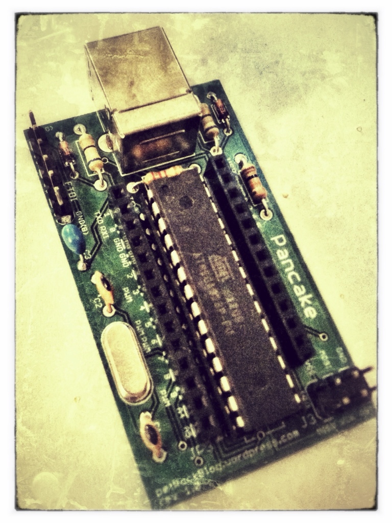
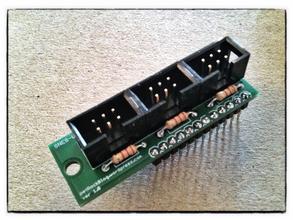
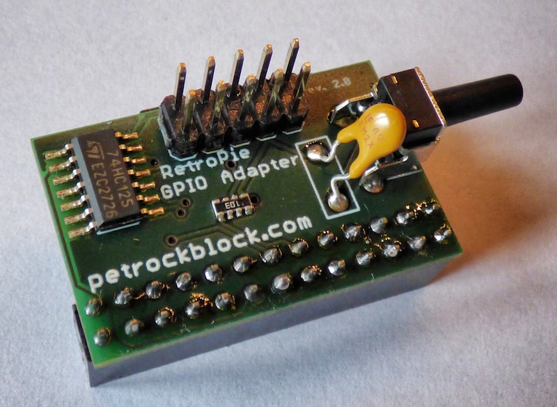
The board layout has two goals: First, it should be as small as possible to keep the costs low and make it usable in as many projects as possible. All pins of the microcontroller have a connection wit a header pin. And, second, the pin out and the footprint of the headers should match with the ProMicro board. While this might (by far) not be a widespread standard, it fits perfectly to the SNES-adapter board that I presented some time ago. The dimensions of the board are only 1.3in x 2.3in (33mm x 58.4mm). After the assembly the board looks like this:

Here is an image strip of the assembly:
- DIP socket

- Resistors
- Zener diodes and resistor
- Capacitors and crystal
- Female headers and ISP pins


- FTDI pins and USB connector

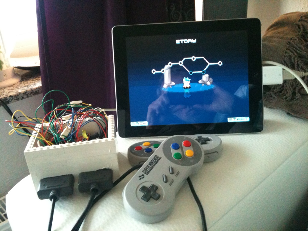
I used the Pancake Board for a remake of my SNES-Controller-iPad adapter. While connecting the Pancake Board with the SNES-adapter board I realized that it would be of advantage in future projects, if the ISP header would be rotated and have more space to the female header. Thus, I already slightly revised the board layout accordingly.
I am thinking about making this board more easily available, for example, as a self-assembly kit. If you are interested in this board, just send me a mail!
Comments are closed.