Homepage › Forums › RetroPie Project › Peoples Projects › SnesPi project
- This topic has 22 replies, 8 voices, and was last updated 10 years, 6 months ago by
 rdhanded2.
-
AuthorPosts
-
12/09/2013 at 21:13 #3509
 brooksyxParticipant
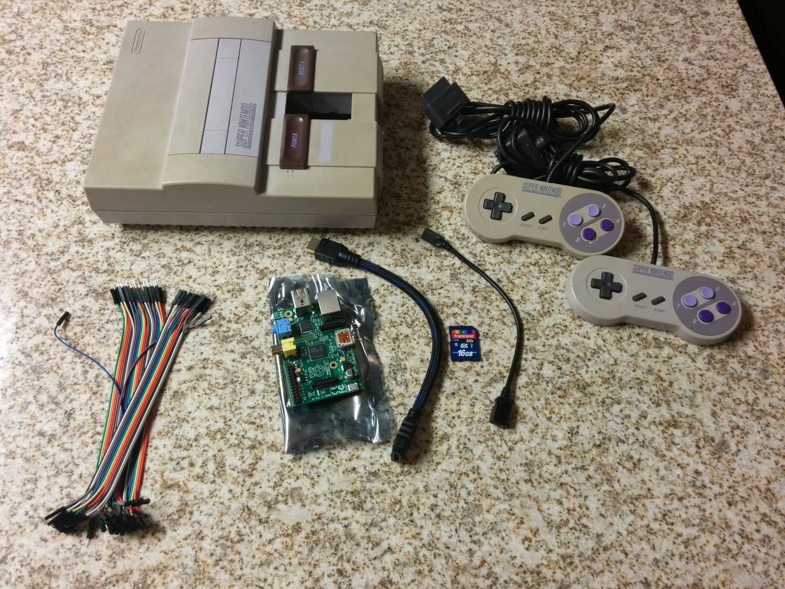
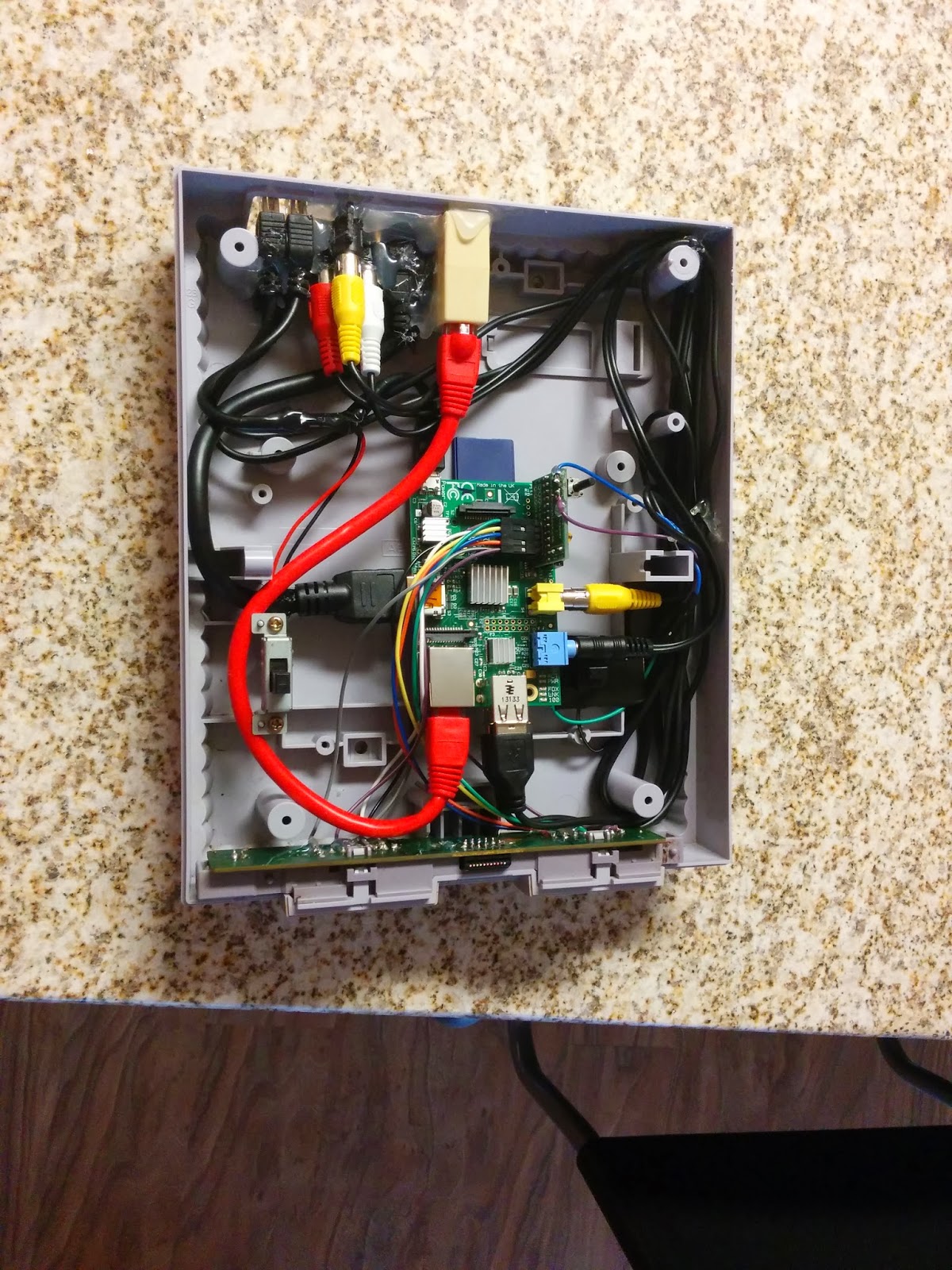
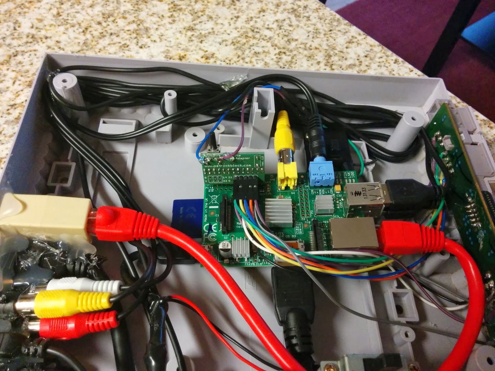
Thought I would share a project I am currently working on. Sure other people have made this before but here is my take on it.
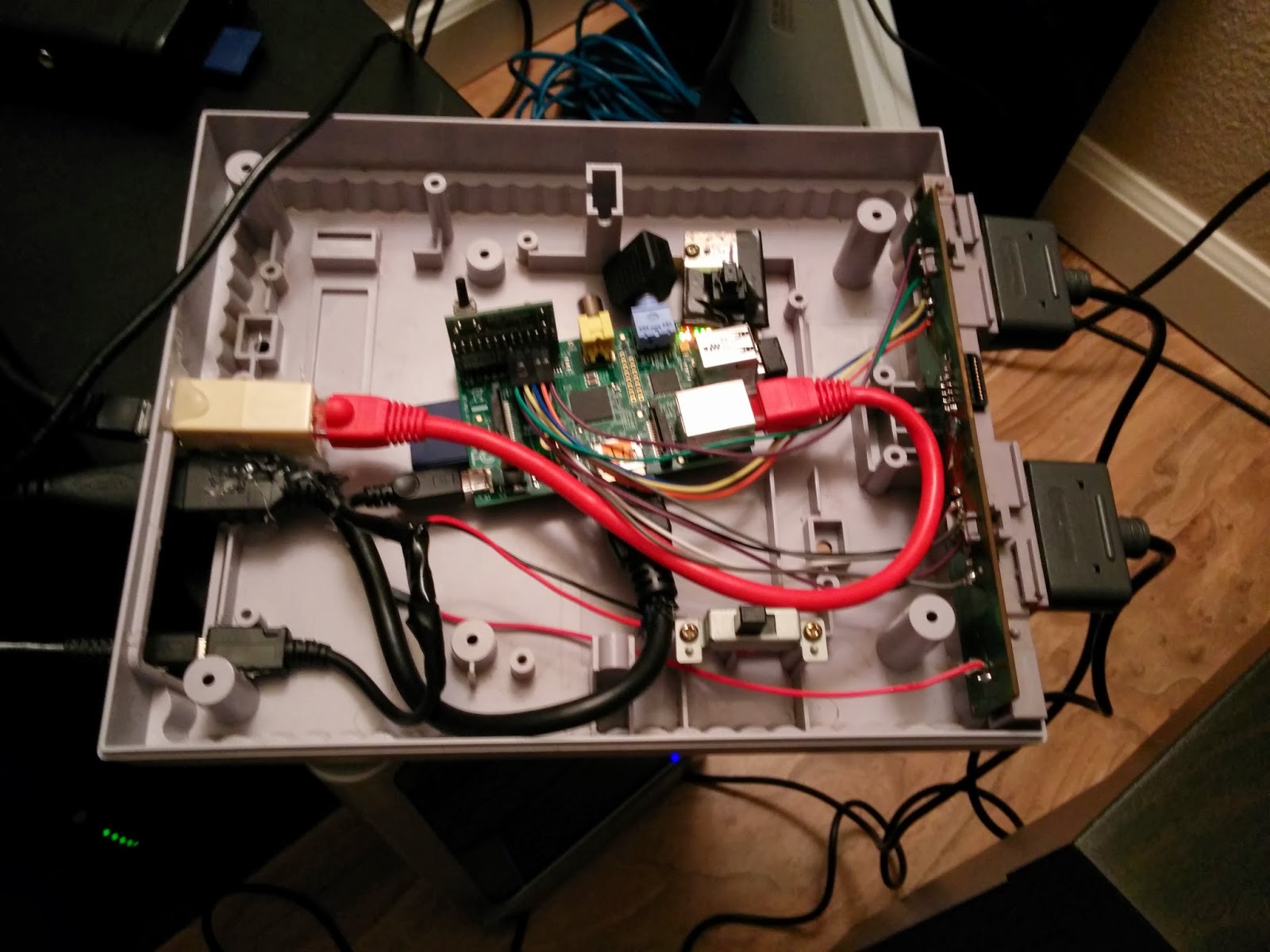
So far most things are working. Wired the SNES power button to the microusb extension cable. I also wanted all of the pi ports accesable so I think I did a decent job cramming them all into the back of the snes. All thats really left is making snesdev reboot with one button press on the gpio adapter, tweaking the emulators and settings, and adding a theme. Maybe a few other tweaks. Here are some pics:
 12/10/2013 at 19:48 #3538petrockblogKeymaster
Looks great – I am looking forward to see some more pics when the other button(s) are working :-)
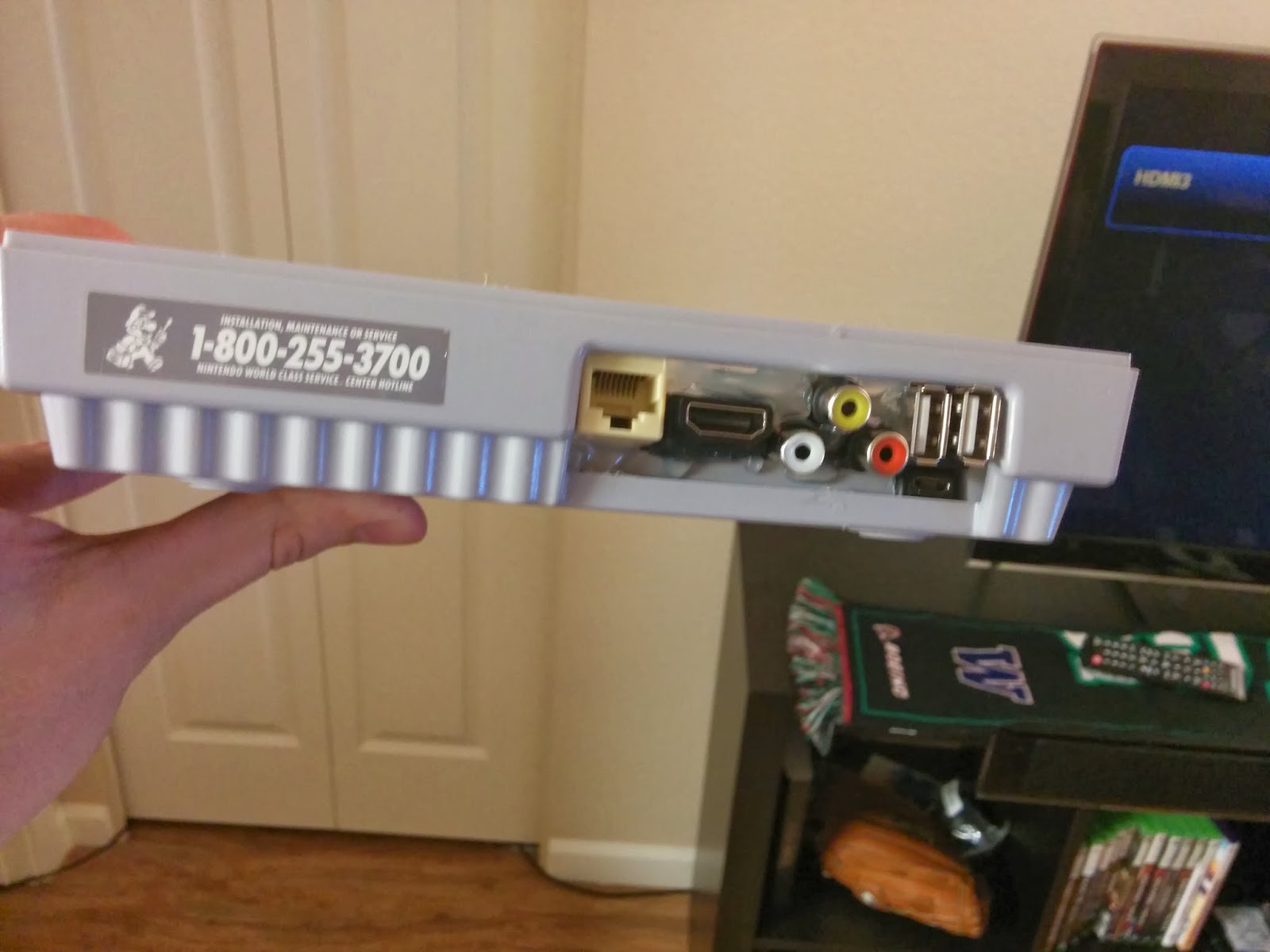
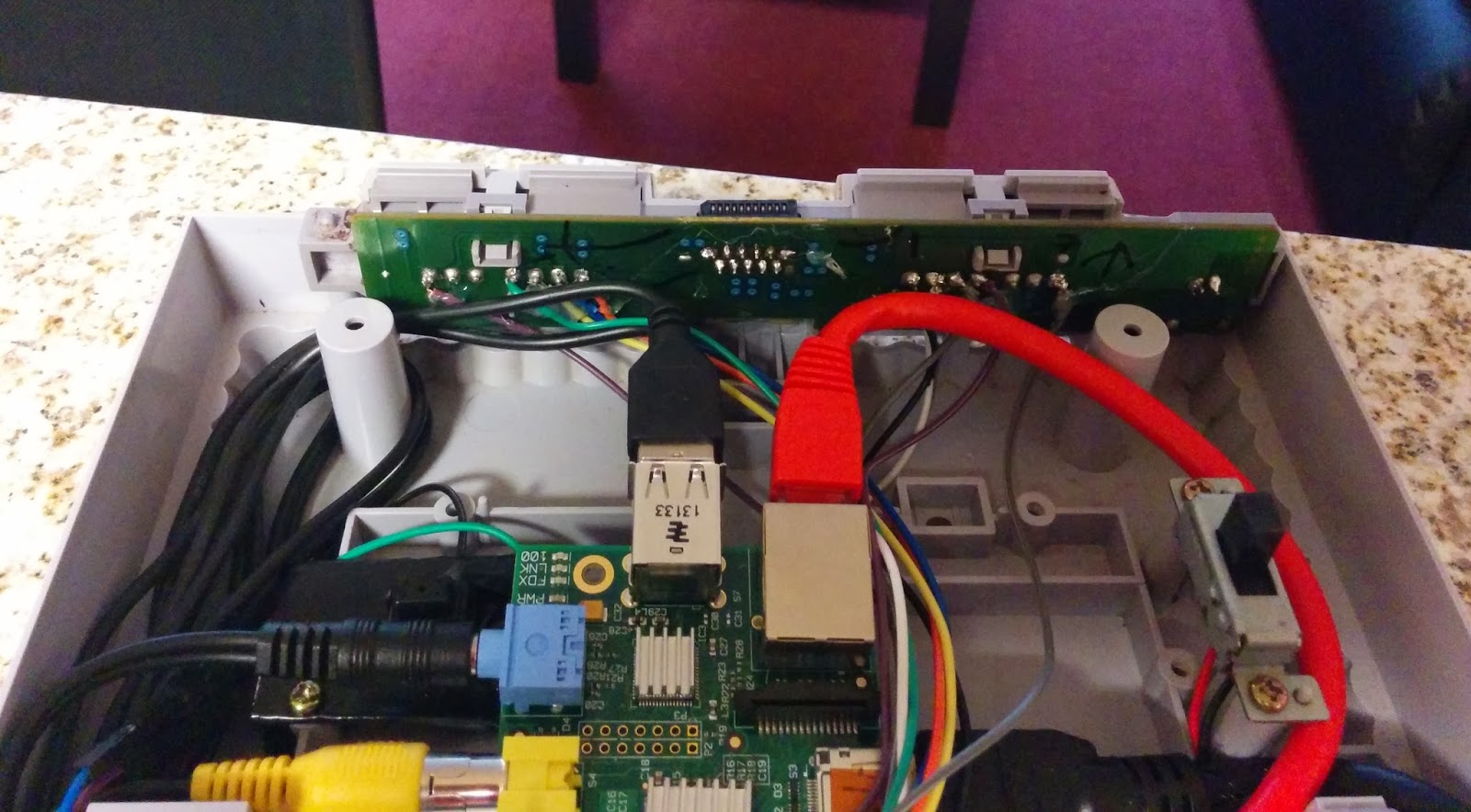
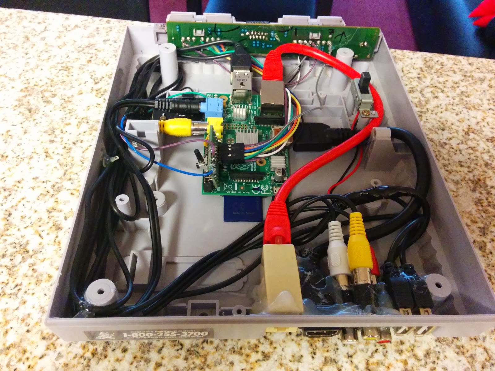
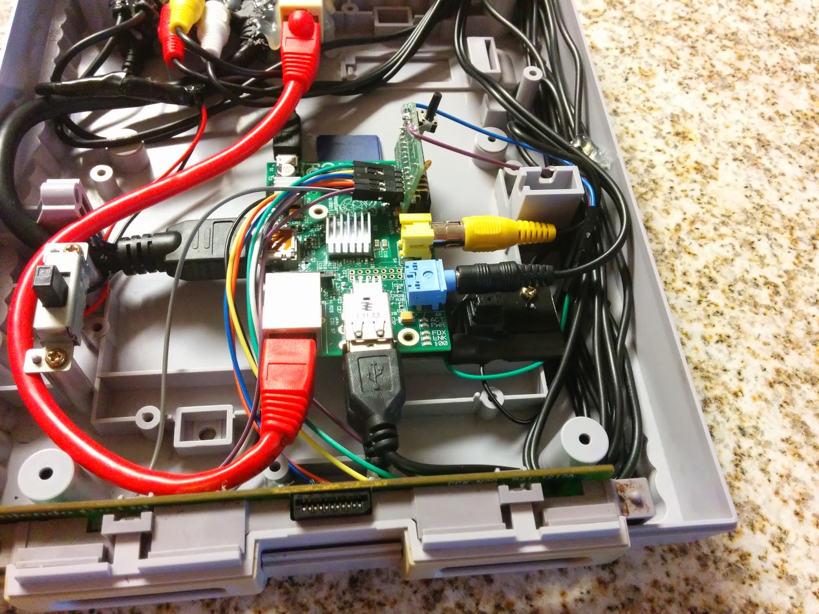
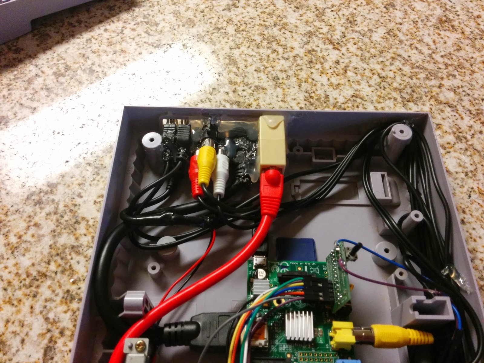
12/22/2013 at 21:08 #3709brooksyxParticipantThought I would post some more pics for you guys. All the hardware stuff is working good and was able to wire up the reset button to a single press brings you back to the home screen. All that is left is setting up the software to my liking. All of the Pi ports are available on the rear of the SNES. Let me know what you think or if you have any suggestions.
12/23/2013 at 18:37 #3718brooksyxParticipantAlso, if anyone wants to see fullsize pictures. Here is my blog where they are located:
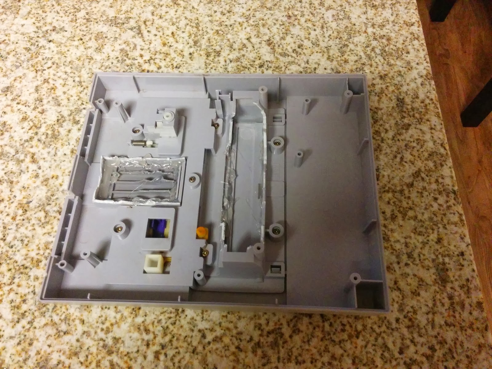
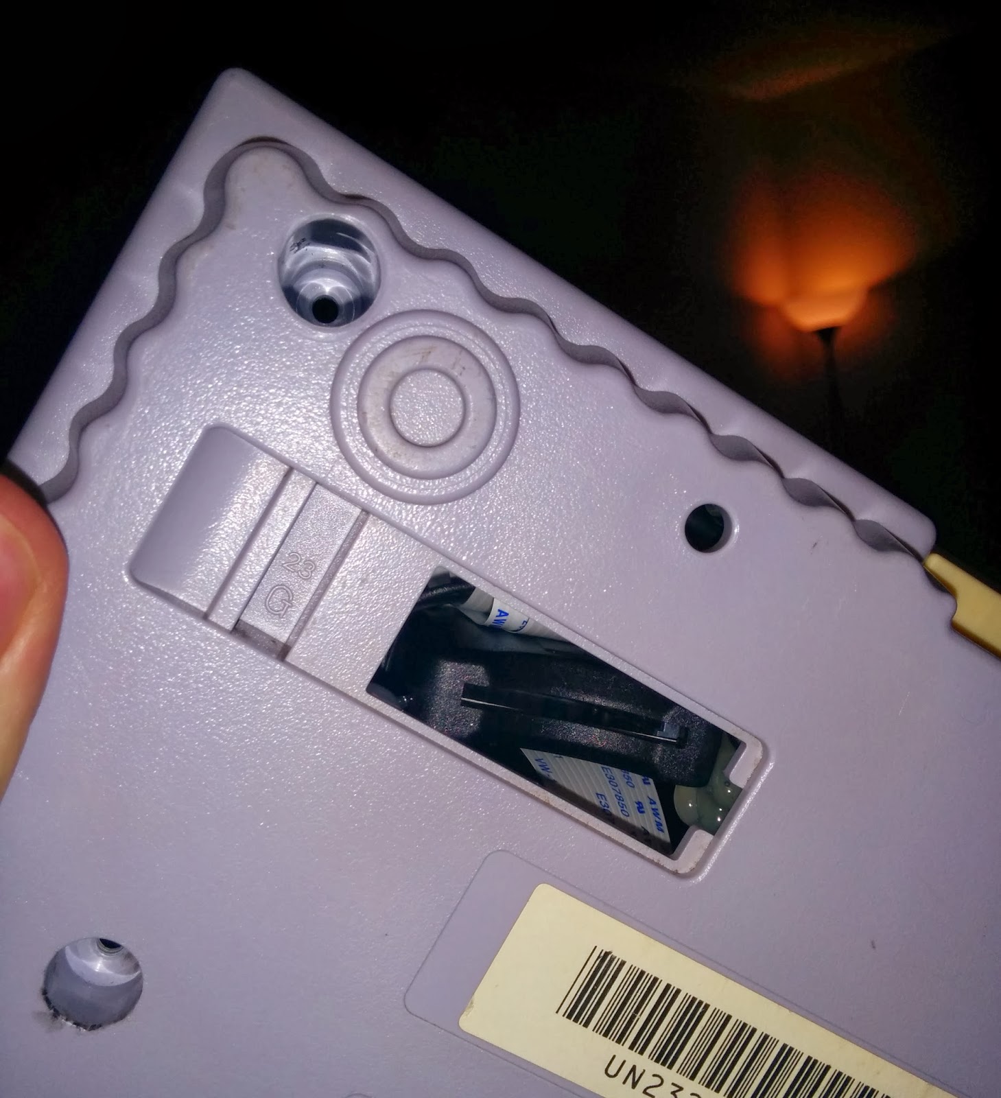
01/15/2014 at 16:53 #4163brooksyxParticipantAnother quick update on my project. I wanted to be able to remove the SD card without having to take the console apart. This is just in case the card gets corrupted, need to do a fresh update, or use a different OS on the system. The solution was to buy an SD card extension cable and position it above the SNES expansion slot on the bottom. Here are the pics (note I had to undo the cable, it wouldn’t boot like that. It was fine when I ran the cable to the front of the case and back, with only one bend.)
01/17/2014 at 22:05 #4236trimmtrabbParticipantGreat work, really tidy. Could you tell me how you wired the SNES power button to the micro usb cable and what tools I would need to do this? Also what filler/resin did you use to set the extension ports in the back of the SNES?
01/17/2014 at 23:04 #4237brooksyxParticipant[quote=4236]Great work, really tidy. Could you tell me how you wired the SNES power button to the micro usb cable and what tools I would need to do this? Also what filler/resin did you use to set the extension ports in the back of the SNES?[/quote]
Thanks, It was a fun project and I am still tinkering with it when I have time. As for the power button I bought micro usb male to female extensions cable and removed the rubber shielding in the middle then I cut the red wire (+5v line) in half. Then I soldered one end of the snes power button wire to one half of the usb wire and then other halves together. So when the SNES button is on the circuit will be closed and allow power to run through it. And when off the circuit is open.
As for filler I just used hot glue. Its not the best but it gets the job done. I just wanted to hold the ports in place and it worked out well. The Raspberry Pi doesn’t get to hot so not worried about the glue remelting.
The tools I used are pretty basic:
Solder Iron
Dikes/Tin Snips
Rotary Tool/Dremel
Hot Glue
Gambit to open SNES (replaced w/ regular phillips screws)
Hacksaw (to cut off the reset button from the original SNES PCB)Feel free to ask anymore questions, always glad to help.
01/18/2014 at 16:09 #4245trimmtrabbParticipantHi, thanks for the quick reply! Think i’m going to get a faulty PAL SNES off Ebay, looks like the same power button as the USA SNES:
So I need to solder half of the red usb +5v to the red SNES power button wire and the other half to the black wire, does it matter which order? Would twisting the wires together and wrapping in electrical tape be ok as I don’t have a soldering iron? I see you have the SNES power LED working, would love to get this working too how did you achieve this? Sorry for all the questions, absolute beginner with all this!
Thanks01/20/2014 at 06:52 #4270brooksyxParticipantYeah, sounds about right. You could always twist the wires but I would suggest getting a solder iron. You can get one with solder at radio shack for $10-$15. And no the order doesn’t matter, you just need to set the SNES switch to be able to open and close the circuit. Also does’t matter if you do it with a PAL SNES. You could do this with nes, n64, etc. It is just a case.
01/20/2014 at 16:07 #4273trimmtrabbParticipantAh great, thanks for the diagram! Just one last question, I was planning to purchase one of these LED’s with a built in resistor: http://www.maplin.co.uk/p/5mm-red-led-ck46a for use as power indicator for the SNES case. Is it possible to plug this LED straight into a pair of female to female jumper leads and then into the 5v & ground pins on the Pi (making sure the long and short leg are connected correctly) Would this leave enough power for the usb ports? (running a flash drive and a usb pad)
Thankyou01/20/2014 at 17:23 #4274brooksyxParticipantYeah, it should be fine to wire it up like that and I wouldn’t worry about the power draw of the LED, they are really low. I didn’t need to add a power led to my system. The one on the controllers ports of my snes just lights up when the system turns on. But as you can see in the picture I wired the ports to the gpio adapter and that is where it draws its power.
01/22/2014 at 00:04 #4301trimmtrabbParticipantah great, thanks for your advice. Will report back when I have finished the project
01/23/2014 at 18:13 #4334brooksyxParticipant[quote=4301]ah great, thanks for your advice. Will report back when I have finished the project[/quote]
Good to hear. Kind of jealous that you got a PAL system. I would love to do another one of these setups with a super famicom. The NTSC SNES looks okay but the SFC/PAL SNES are so much more purdy.
05/05/2014 at 09:49 #6624AnonymousInactiveCheck out mine version :)
07/04/2014 at 21:46 #12106zSprawlGuestPretty cool. This post has inspired me to copy you. :)
09/15/2014 at 16:28 #66167brooksyxParticipant[quote=12106]Pretty cool. This post has inspired me to copy you.
[/quote]Cool, got any pics?
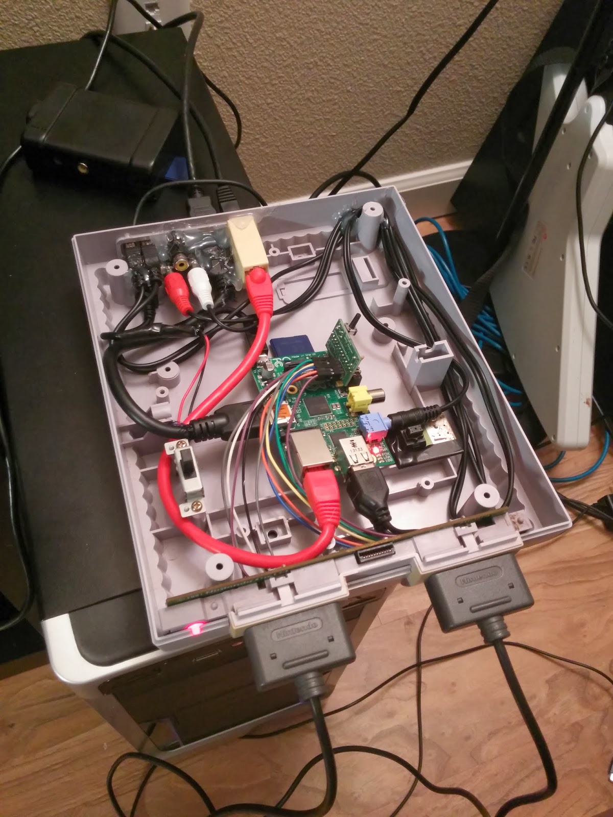
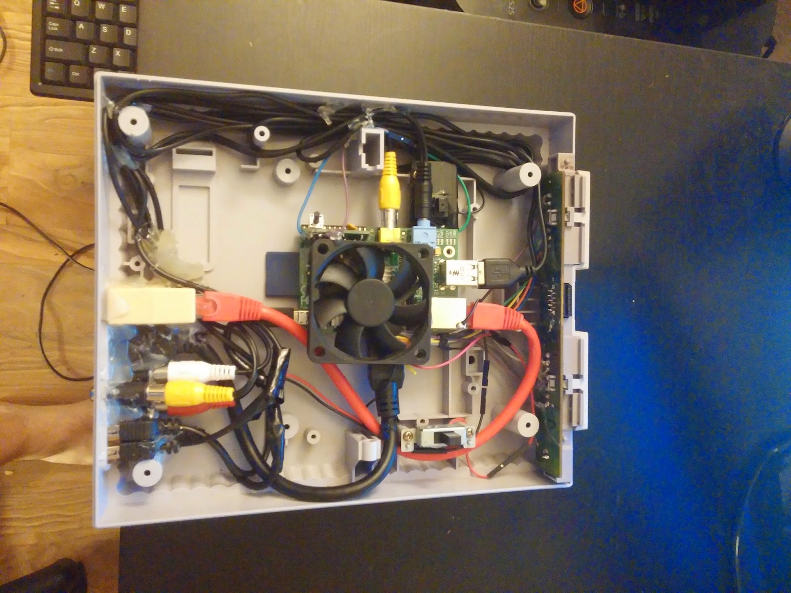
09/16/2014 at 09:00 #66717brooksyxParticipantNew picture, added a fan to keep the Pi cool.
05/31/2015 at 20:26 #98829goobatroopaParticipantGreat project bro. Could you explain in more detail how you wired up the reset button. I’m going to start my project this week and I’ve been struggling to find anyone who can explain it.
06/13/2015 at 12:21 #99741EkDorParticipantcool
06/13/2015 at 12:23 #99742EkDorParticipantThis is one I was planning on doing but with some script changes.
http://iot-projects.com/index.php?id=raspberry-pi-shutdown-button
12/09/2015 at 21:25 #111516brooksyxParticipant[quote=98829]Great project bro. Could you explain in more detail how you wired up the reset button. I’m going to start my project this week and I’ve been struggling to find anyone who can explain it.
[/quote]
Hey I know this was from a while ago but for the reset button I cut out the corner of the SNES motherboard where the reset button hits and then wired those two wires to the gpio button push pin. Then screwed that part of the motherboard back into the base. Hope that makes sense.
12/09/2015 at 23:19 #111523rdhanded2ParticipantI saw another user one here who used a microswitch and a hair tie. I did that and it works great. I will find a pic that I have and post it.
12/09/2015 at 23:24 #111524rdhanded2ParticipantThis pic is from severdhed of his build. I did similar and it works well for me.
-
AuthorPosts


- The forum ‘Peoples Projects’ is closed to new topics and replies.