Homepage Forums RetroPie Project Everything else related to the RetroPie Project Using other GPIO Pins with the RetroPie Adapter

Viewing 5 posts - 1 through 5 (of 5 total)
  • Author
    Posts
  • #2976
    tman140
    Participant

    I would like to use two other GPIO pins, and wondered if it would be possible with the adapter. What pins are available and, if any are, how would I wire into them?

    (Sorry if this has already been posted, though I didn’t see anything when i ran a few searches)

    #2978
    petrockblog
    Keymaster

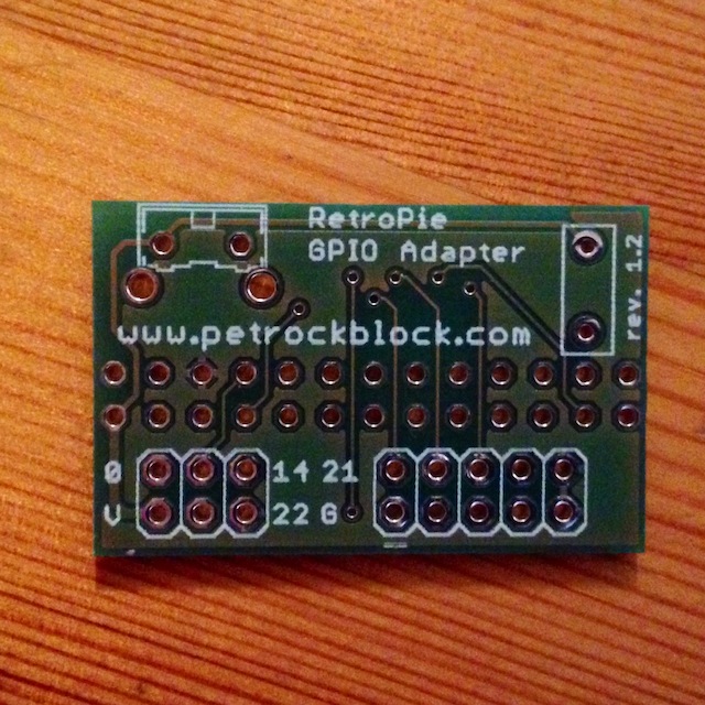
    Yes – the adapter breaks out four additional pins: 0, 14, 21, and 22. The schematics of the RetroPie GPIO Adapter are available at https://www.petrockblock.com/?wpdmdl=7. In addition, GND and 3.3V are broken out.

    I hope that helps!?

    #2992
    tman140
    Participant

    That helps a little bit, although i am unsure where the pins are broken out on the actual board???

    #2996
    petrockblog
    Keymaster

    You could access the pins, e.g., with a 2×3 male header. I attached an image that shows the PCB of the RetroPie GPIO Adapter:

    RetroPie GPIO Adapter PCB

    #2998
    tman140
    Participant

    Ah, I see. I have the board (haven’t assembled it yet) but didn’t notice the markings that showed which pin is what. Thank you for your help and awesome project!

Viewing 5 posts - 1 through 5 (of 5 total)
  • The forum ‘Everything else related to the RetroPie Project’ is closed to new topics and replies.