From Arduino to Breadboard with a Minimum Configuration
Jun

After having finished my first projects with an Arduino I started to look for ways, which would allow me to port my project to an Arduino-compatible minimum configuration board. Ideally, I wanted it to be much cheaper than a new Arduino board. In this post, I describe how to put together a working protoype on a breadboard that can easily be programmed with the Arduino IDE afterwards.
The Arduino Duemilanove, which I used for my projects, uses a through-hole ATMEGA328 microcontroller. The currently new Arduino Leonardo uses an enhanced SMD version of the microcontroller. Using SMD parts allows a very compact PCB design and the components are mostly cheaper than their through-hole alternatives. The caveats, however, are that SMD components are more difficult to solder and the equipment needed for soldering is more expensive. Thus, I decided to work with though-hole components only. In the following, I describe how to build a minimum configuration for using an ATMEGA168 or ATMEGA328 which can be programmed with the Arduino IDE. A major difference to an Arduino board is the lack of the USB socket for programming the microcontroller. In our case, we are using the in-system programming (ISP) capability of the ATMEGA and, thus, make use of a so-called programmer. This is a piece of hardware, which is available in many forms and from many different companies. In simple words, it is that piece of hardware that lets you transfer your program onto the microcontroller. The question, which programmer I am using, is answered later in this article.
There are quite a few tutorials and minimum ATMEGA boards out there so that it is quite easy to get an idea about the essential parts of a minimum configuration board. I found these quite useful:
Another help was a close look at the “Sippino“, which is a minimum-configuration Arduino-compatible board. With the given schematics of that board, you can already start to build your own stand-alone, minimum configuration ATMEGA board. Now, you could ask “Why don’t you just buy the Sippino, if it is exactly what you want to build?” Well, first, we are all curious and want to know, how things work. And second, having build an stand-alone ATMEGA board on your own is fun and, furthermore, allows you to easily extend it to your needs.
Ok, let us start with the needed parts. I used the following list of components:
- 1x ATMEGA328
- 1x Crystal with 16 MHz
- 2x Capacitor with 22 pF
- 1x Resistor, 10k
- and, of course, a breadboard and some jump wires
In constrast to the second tutorial listed above, I decided to use a crystal instead of a resonator, because I have the impression that crystals are easier to buy at various electronics distributors. An ATMEGA could also be used without any external crystal, because it already has an internal one. However, in case of the ATMEGA328, for example, the internal crystal has a clock rate of 8 MHz, which is only half the speed of an Arduino Duemilanove. And since we want to build a board with a microcontroller, which can easily be programmed with the Arduino IDE, we just stick to the Arduino configuration that makes also use of an external 16MHz crystal. By the way: The differences between a resonator and a crystal are summarized in this easy-to-read article from Sparkfun. I put everything together according to these schematics:

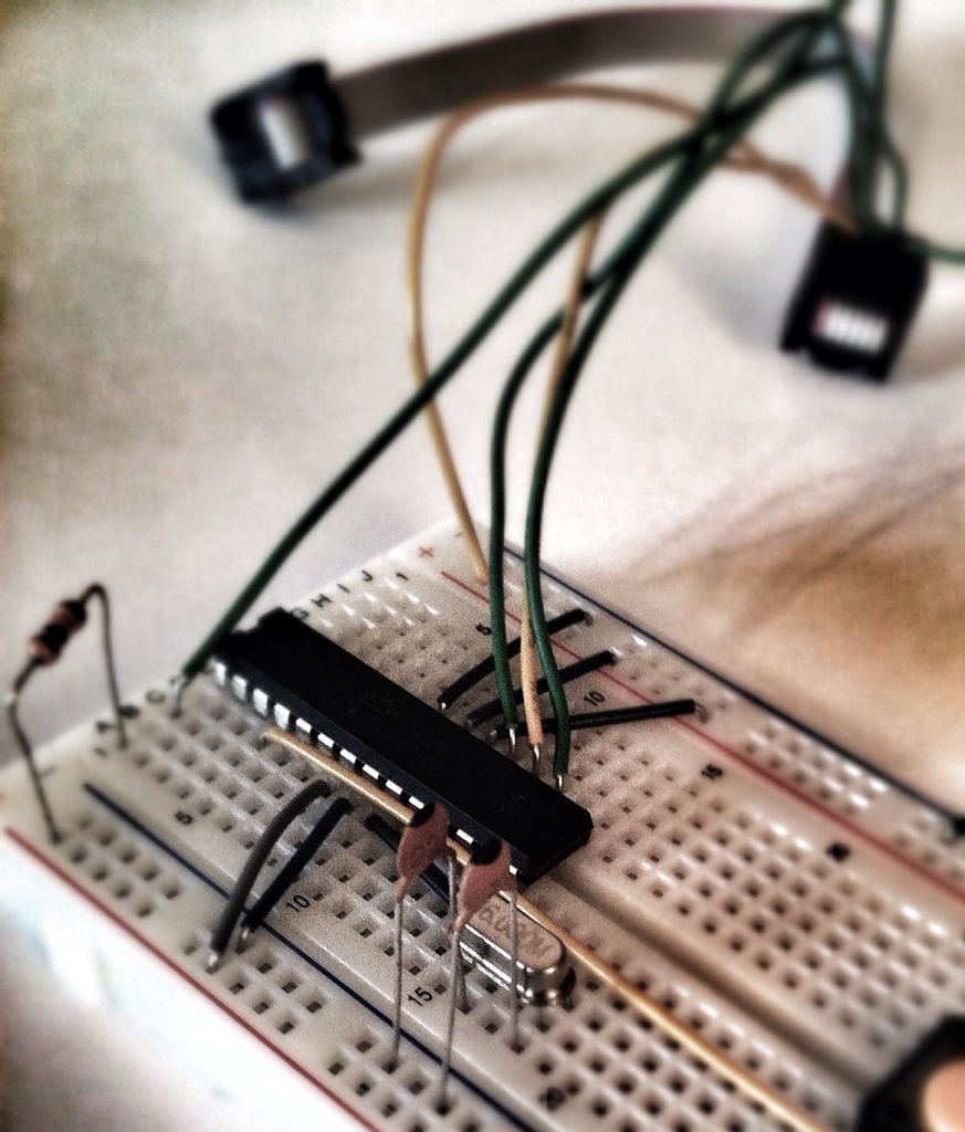
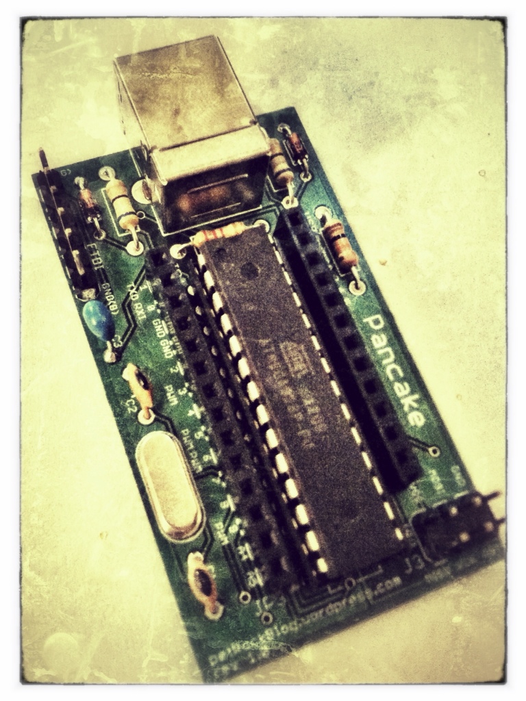
You can find a nice overview about the pin out of the ATMEGA328 here. This is how everything looked afterwards:

In the image you can also see that the ISP connector is already connected to the board. Therefore, you have to know the pinout of the ISP connector. A quick search for “ISP pinout 6-pin” leads to the AVR documentation which also provides the pinout for the 6-pin ISP socket that we are going to use:

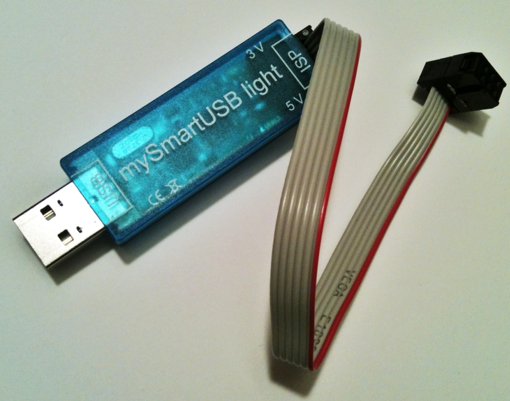
There are drivers for Windows, Linux, and for Mac, and the installation of the driver was done within seconds on my notebook. In order to use this programmer with the Arduino IDE, we have to add it to the list of available programmers. The file that we are looking for is called “programmers.txt”. The absolute path depends on your operating system. In case of MacOS, you find the file “programmers.txt”, if you
- Right-click on the Arduino application file
- Select “show content”
- Go into the folder “Contents/Resources/Java/hardware/arduino”
Using Finder, this might look like this:

Here is a screenshot of the modified version of “programmers.txt”:


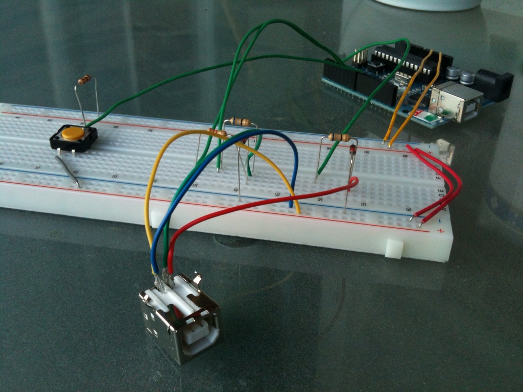
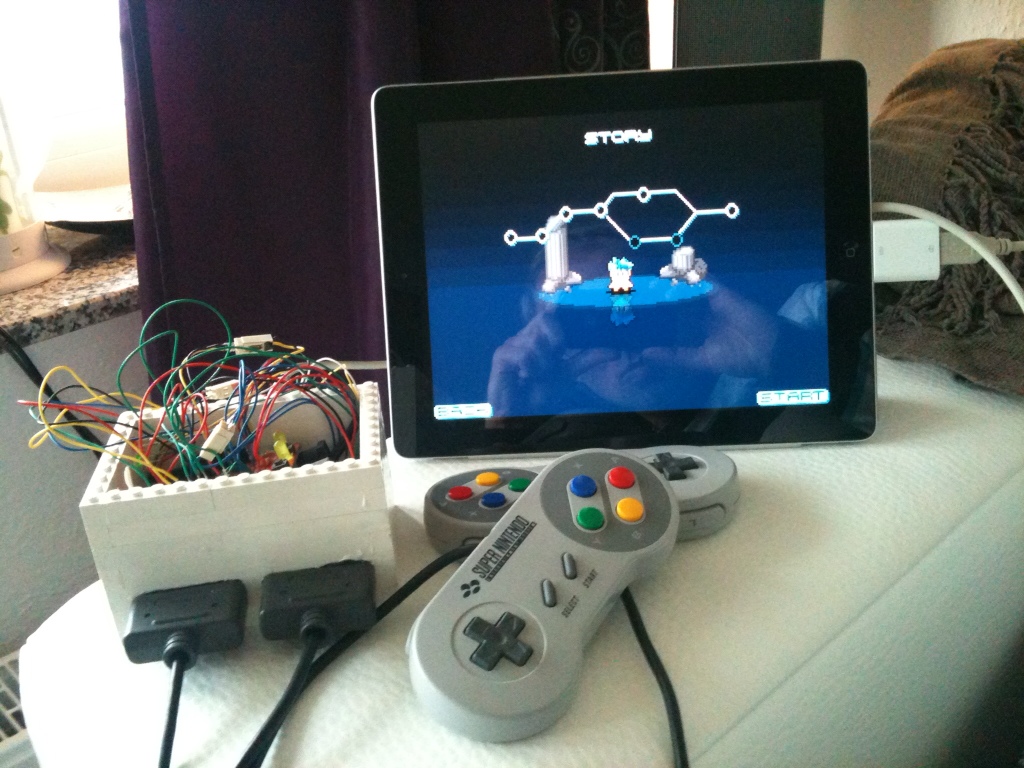
If you do not press the shift key, the upload will fail. It took me some time to find out this “little” detail. If everything is connected correctly, you could, for example, go on and upload the “blink” program. Again, if you are wondering which pins within the source code belong to the hardware pins on the breadboard, you can find a nice overview for the ATMEGA328 here. One important thing was not mentioned yet. In this setup, you need to power your circuit with an external 5V power supply. For now, you could just connect the 5V pin of your Arduino board to the VCC pins of the microcontroller, as well as the GND pin of the Arduino board with the ones of our standalone board. In the next article, I present a handy little board, which is powered by a USB connection.
With this setup, you are able to build your own microcontroller projects for much less than you would pay for an Arduino. And, as you have seen, it is actually quite easy and involves only a few components!
If you have any questions or comments, I would be glad to get them!
For a really easy Arduino design check out ours: http://www.dcoptimum.com/arduino-breadboard/
You saved me!!! You are the only one who said that we have to press “shift key” to success!! Else I had a “avrdude: stk500_getsync(): not in sync: resp=0x00” error!!!! Thank you thank you!!!
i am using an avrispmkii. i did evrything correct and also edited the boards .txt file but every time i upload my sketch to the breadboard, i get an error which says wrong microcontroller found