New Revision of the PowerBlock: Increased Flexibility

May
The PowerBlock is a small support shield for the Raspberry Pi that provides a power switch functionality. Recently, we have updated the design of the PowerBlock such that it now offers an even greater flexibility regarding the connections with the Raspberry Pi.
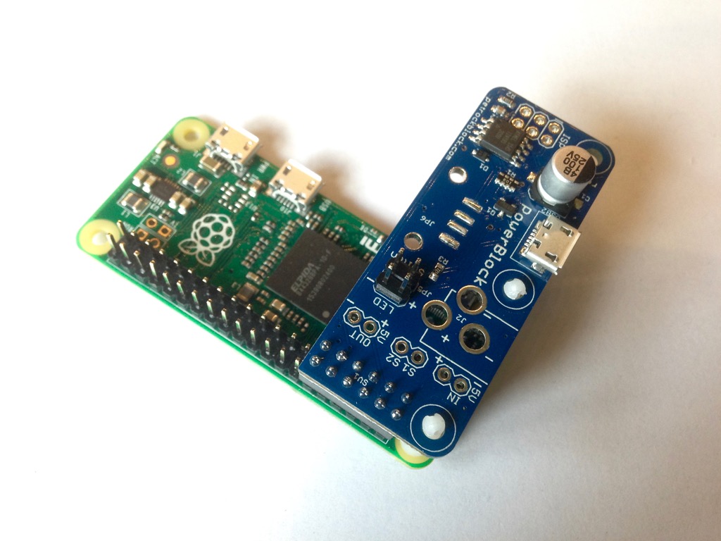
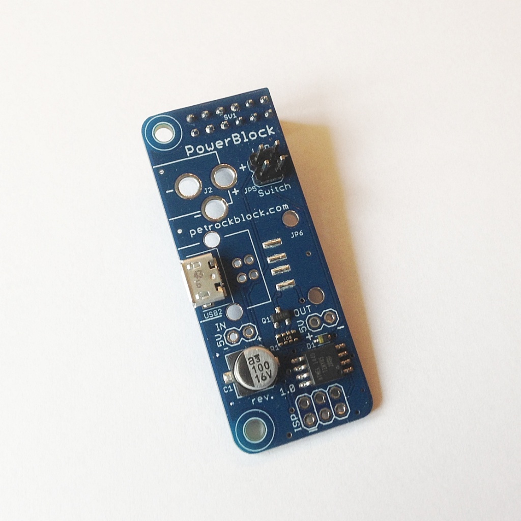
Here is an image of the new PowerBlock Revision 1.1:
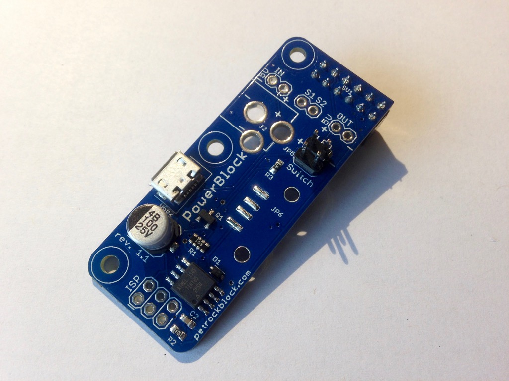
Besides some fine tunings in the board layout, these are the major differences to the previous revision of the PowerBlock:
Additional signal breakouts – input voltage, output voltage, and control signals
All the signal above can now be attached to the Raspberry Pi without using the 2×6 pin connector. As you can see on the image below, there are individual pin outs for the 5V input voltage, the 5V output voltage, as well as for the control signals S1, and S2.
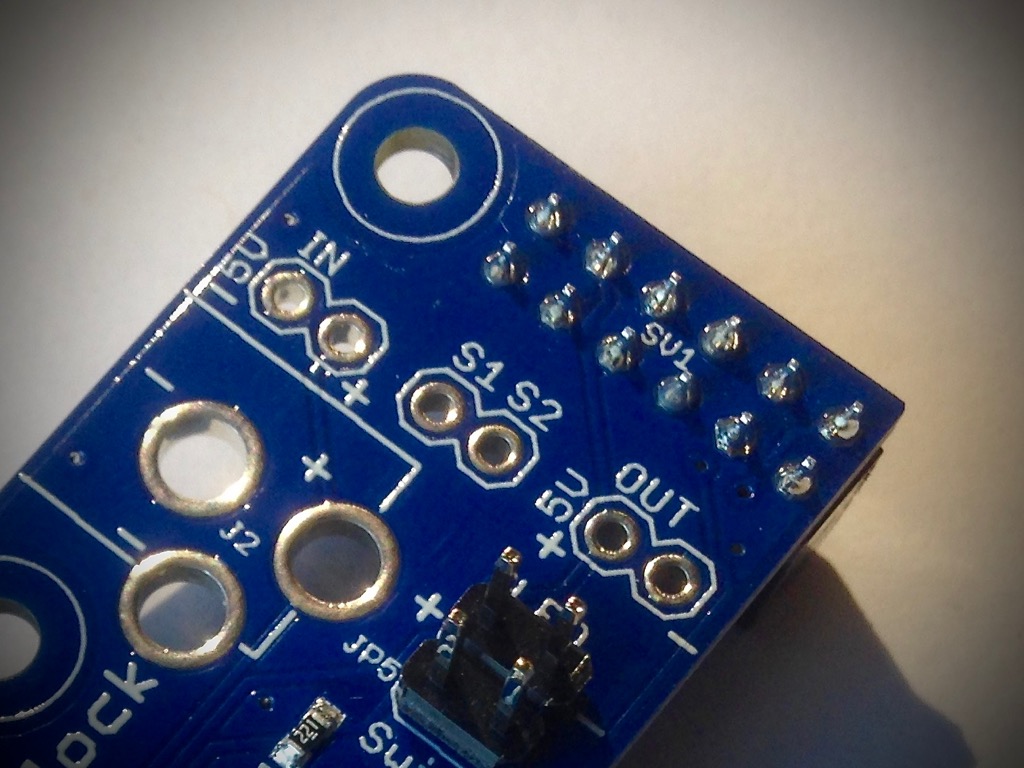
The pin out is as following:
5V IN, +,-: supply voltage
S1: pin 12
S2: pin 11
5V OUT +: pin 2 or pin 4
5V OUT -: pin 6 or pin 9
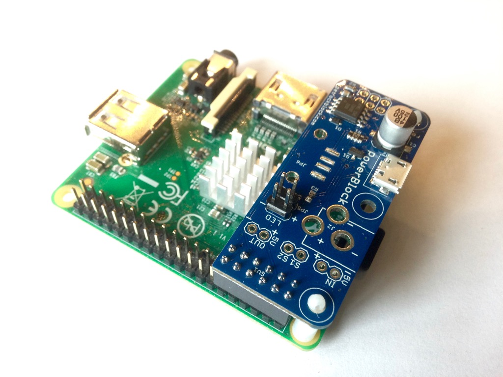
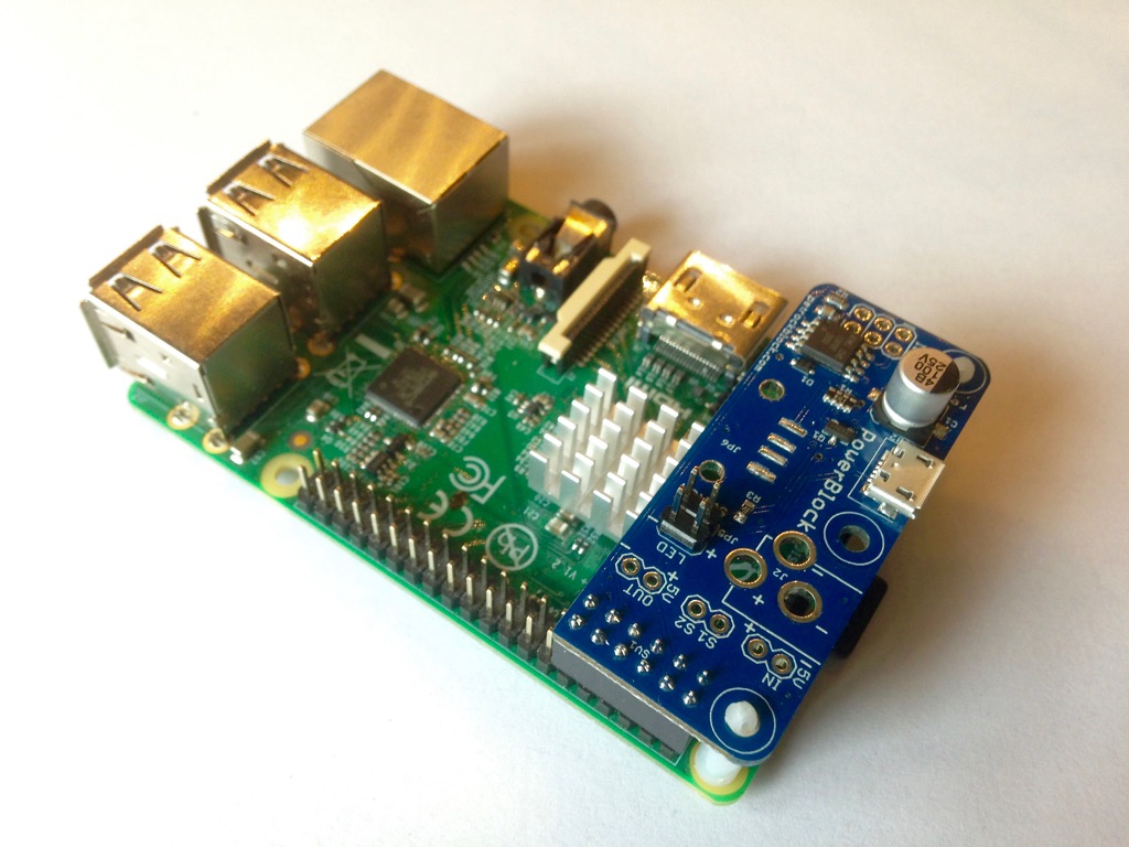
Additional mounting hole for attaching a Raspberry Pi Zero
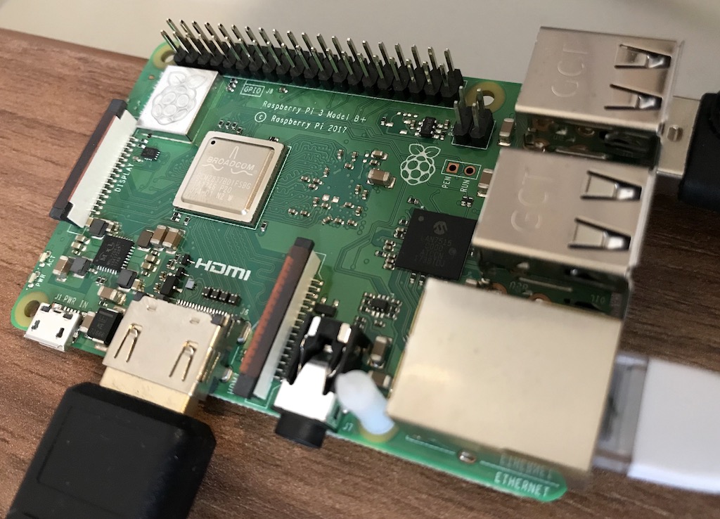
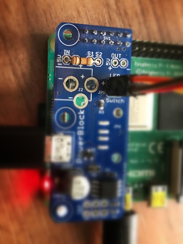
This addition makes it possible to not only mount the PowerBlock to the Raspberry Pi model A and B, but also to the Raspberry Pi Zero. Here are some exemplary images for the various models:
| RPi Model A | RPi Model B | RPi Zero |
|---|---|---|
 |
 |
 |
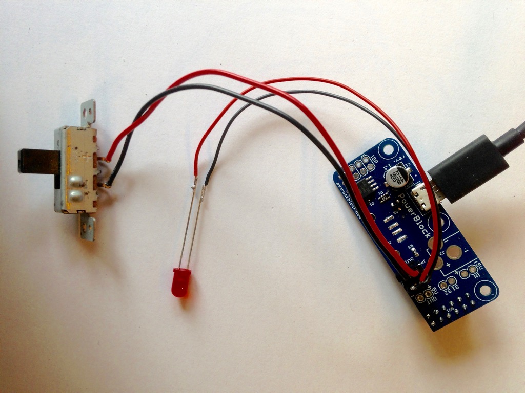
Together with a toggle switch the PowerBlock provides a reliable and safe power switch functionality for the Raspberry Pi. An optional LED can also be attached to the PowerBlock that serves as a power status indicator.
You can find more details and a comprehensive installation and configuration description on the description site of the PowerBlock.


My power lock works just fine for the Raspian OS but for retropie it DOES do a clean shutdown when the switch is set to off BUT unlike in Raspian it will NOT power the Pi3b off from retropie like it will for Raspian.
Any ideas or thoughts? I use the exact same install procedure for both OSs of the driver with out any errors.
I have not heard of this yet. Is the PowerBlock driver successfully installed on RetroPie?
Which version of RetroPie are you using?
Hi. My PowerBlock has arrived today, but I am having problems to run it properly in my C64 retropie. I use this switch (http://www.pollin.de/shop/dt/OTc2OTc1OTk-/Bauelemente_Bauteile/Mechanische_Bauelemente/Schalter_Taster/Miniatur_Drucktaster.html). There are 2 kinds of it, “open when pressed” and “close when pressed”. If I use “close as pressed” and press the switch, then pi starts up and immediately shuts down by itself. If I use “open as pressed” pi powers on without pressing switch. When system is up and I press switch then pi shuts down and starts up again (self reset). What am I doing wrong? Do I need a different switch? Additionally, compiling and installing the driver looks good, but if I do “service –status-all” then I don’t see a “+”, but a “-” in PowerBlock line.
I have replaced the reset switch with a toogle switch (also push-button style), now it works like a charm.
Glad to hear!
Hi, Can I still use this when I have pin 11 and 12 already occupied? Can I alter the driver to use diffrent pins for instance?
Never mind. Just found out I can. :)
I must be blind. Where did you find to change the signal pins?
Hi
I can’t get the “mkdir build && cd build” to work I get “-bash: syntax error near unexpected token ´;&` ?
It seems that there is an invalid semicolon. Maybe the instructions in the repository at https://github.com/petrockblog/PowerBlock#building-and-installation give you another hint for the installation.
silly question , where would i connect the fan on the powerblock. would it be on the pin out? if so which one would i use?
Yes, it would be the 5V “out” pins.
Hi there, sorry to be rude and jump in on this conversation, but I was wondering if you wouldn’t mind pointing me to a circuit diagram of the v1.1 of the powerblock. I wanted to add another switch so that I could watch the input to trigger an amount of my flash drive
Currently, the schematics of the PowerBlock are not made publicly available, sorry. That might change in the future, though.
Hi there,
I have a couple of questions regarding the powerblock v1.1. So if anyone has an answer/s, if you could please respond to this post.
Where can I download the attiny85 code from, What is the dev environment that is used to change the code/firmware on the attiny85? Which ISP was used to program the powerblock,
What is the pinout for the powerblock ISP pins
Thanks
Hello, my project is a pi3B with retropie in a snes housing.
What will happen when I use the powerblock and put a reset switch (open when pressed) in line to the toggle switch.
Will it perform a soft reset when I press the Reset Switch?
Did the Powerblock contains a fuse that will do the work instead the fuse on the Micro USB Port of the Pi?
Is it possible to do updates on the powerblock, if new features would come?
Reading through their blog I think it would just start a shutdown but depends on how the ATtiny is programed to whether it would start back up immediately after it is fully off. I would suggest connecting the reset switch to an open GPIO on the Rpi then write a short script that initiates a “sudo reboot” when pulled low (make sure to set the pullup on that pin too).
There is an ISP header on the board that should allow one to update the ATtiny.
The PowerBlock driver will initiate a shutdown. When the RPi has shut off, it will immediately turn on again. The PowerBock does not contain a fuse. However, it contains an transient-voltage suppression. You can update the PowerBlock firmware via ISP. You need to have the tool for that, though.
Do you have a schematic? Any plan to add a battery monitor?
Have you seen this:
https://www.raspberrypi.org/forums/viewtopic.php?t=41849
That uses quite a few GPIO on the Rpi, and quite a few components that all will draw some amount of power even with the Rpi off. I would rather see the battery monitor integrated into the ATTiny on the power switch which could be handled by doing a ADC measurement on VIN. Though might require moving to a ATtINY85 20pin, or could use a ATtiny84 14pin
Something like this: https://github.com/cano64/ArduinoSystemStatus
Hi,
Is it possible to use a latch switch with the powerblock or does it only work with a toggle switch ?
thanks
Hello Joshua,
right now, only a toggle switch is supported. However, we plan on supporting momentary switches with an upcoming firmware release.
Do you have a eta on the upcoming firmware to support the momentary switches?
This is one of the most elegant pieces of kit for RPi projects I have ever used. Many thanks for all the work on this. Works as advertised.
I have a query as I wish to use the board wired from the new 1.1 pinouts into the Pi for space reasons.
Clearly the wiring is as follows (but want to check before I burn anything):
– power out +/- goes to pins 2/6 to power the Pi
– S1/2 go to pins 3/5 to manage the I2C
this leaves pins 11/12? to what on the Powerblock Board do you wire pins 11/12 to complete the same connections as the shield?
Happy to supply pictures if required?
You are right, I should make that more clear on the website. Here is the pin out for the PowerBlock:
5V IN, +,-: supply voltage
S1: pin 12
S2: pin 11
5V OUT +: pin 2 or pin 4
5V OUT -: pin 6 or pin 9
Many thanks, I will go away and test and publish the final project when done.
Hi there,
The PowerBlock is perfect for the mini arcade machine I’m building. I’ve got it working with a regular switch, but I’d like to use a switch with a built-in LED. I’ve tried wiring one, but it causes the Pi to crash on reboot, then gets caught in a loop of crashes and reboots. Would you be able to show how to properly wire such a switch? (example pic attached)
Thank you for your time.
Unfortunately, I cannot say much about it without a data sheet of that switch. It might be that the internal LED is not working with the 5V power supply that the Raspberry Pi needs or that the wiring with the switch is not correct.
it says 12v on the switch. 12v is that even available on the pi?
Good point. The USB and the RPi pins provide only 5V or 3.3V, respectively.
https://uploads.disquscdn.com/images/f65775611da411071f5bd6518ffdb5adf14d59fb560d36aade349cd9d46b8493.png
Fair point. Here’s a scan of the back of the package. Sorry, it’s the only documentation I have.
I would like use PowerBlock Rev. 1.1 with http://www.orangepi.org/orangepiplus2/ . How do you think. It will be possible? Thanks!
The PowerBlock driver is currently tested on the Raspbian OS image. So, if you run your OrangePi with a Raspbian image the PowerBlock driver should work out of the box. But I am not 100% sure and I am afraid that, in the end, you have to find it out first. I do not have an OrangePi at hand right now …
However, any feedback is appreciated, if you make any experience with that!
Hi,
I’m looking at he PowerBlock for use with RPi 3 and runeaudio, which is an Arch Linux based audio player OS. Can you tell me if the service will run on Arch Linux and if so does it add much CPU load?
Assuming that it is not suitable for my distro and that I’ll have to script a service myself (I’m not much of a programmer but I can copy bits and pieces) could you tell me a little more about what the PowerBlock is sending to the Pi and what it is expecting in return? Eg which pins go high/low at what points in the process.
Many thanks.
Have you already tries to compile and install the PowerBlock driver (https://github.com/petrockblog/PowerBlock) on ArchLinux for the RPi?
No I haven’t as I thought that might cause issues given there was no PowerBlock connected. As it turns out I decided to purchase a PowerBlock anyway as I believe it should work. If not I’ll be able to use it on another project down the track.
How much power can I switch with rev1.1? Is 5v and 2 amps pissible?
The MOSFET on the PowerBlock can handle currents up to 3.7 A. It is designed for 5 V.
One more question. I am going to be using a 4 relay module along with your Revised Powerblock board. The relay requires one of the PI’s DC power 5Volt pins & a ground. Is it safe to say I can solder the VCC 5V power pin of the relay to the 5V + signal breakout, and then the ground would go to the 5V – signal break out?
Sorted this as well. Soldered 2 male header pin in the 5volt out breakout holes. Connected my relay 5 volt ot the 5 volt + on the board, and used a ground on the PI. All is well in the universe again! Thanks!
Glad to hear that you figured it out already! Sorry for this delayed answer.
No worries. Your PowerBlock is great!
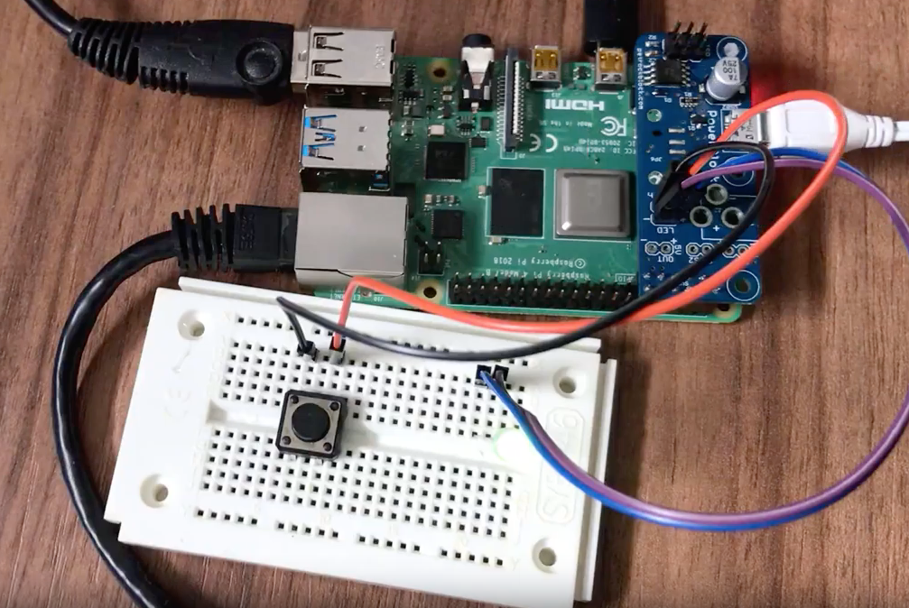
Greetings. I purchased the New Revision of the Powerblock, and it is great! I am curious what size nylon circuit mounting pins you are using to hold the board (opposite side of the GPIO’s) in the attached photo. Any idea where I could get these from? Thank You!
Those are spacers from http://uk.farnell.com/richco/mdlsp1-12m-01/pcb-support-pa66-natural-12mm/dp/1325986.
However, I have just seen that they are not stocked anymore. But I hope that you got an idea what to look for!
Thanks for your reply. I purchased a spacer parts kit with various sizes from Amazon, Worked great.
does this work for pi3 as well?
n/m it does. found out on store.