Review: T962A Reflow Oven Controller Upgrade Package
Aug
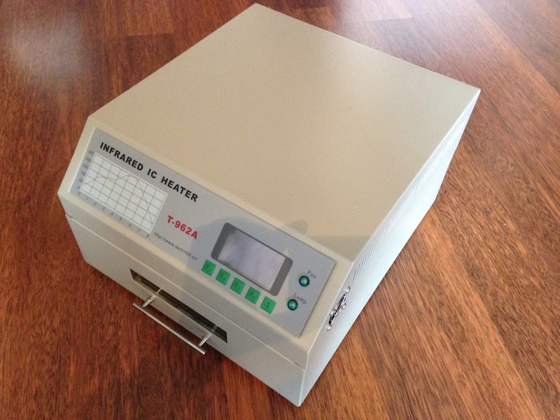
 A while ago I posted a review about the reflow-flow oven T-962A. As written in that post the T-962A has certain flaws: The heat is generated by IR heaters that do not distribute the heat evenly within the oven. This made the results of the soldering processes unreliable. Also, the responsiveness of the user-interface is not that good: Tuning the reflow profile is tedious.
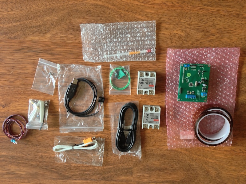
Recently, I got an upgrade kit for the T962A from ESTechnical that promises to enhance the oven in exactly these aspects. This post is about the installation and review of the new functionalities of this upgrade kit.
Installation
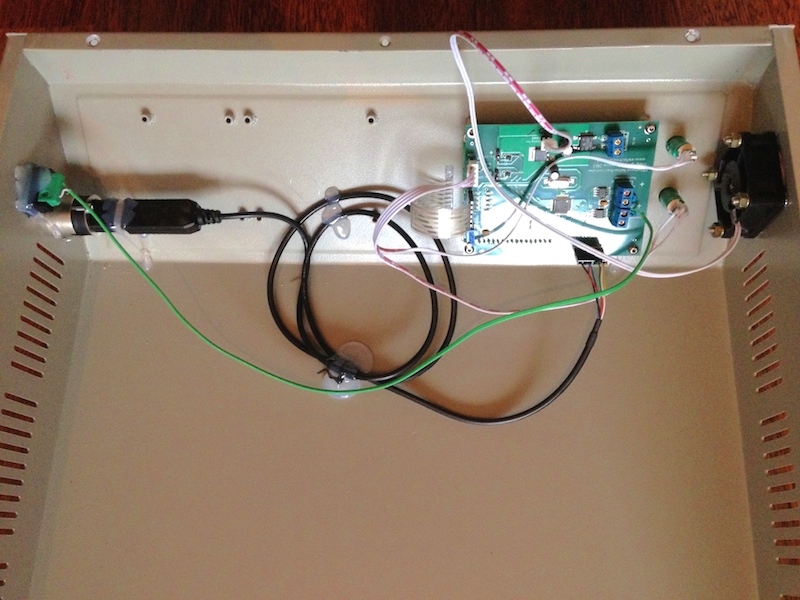
The upgrade kit comes with a step-by-step installation guide (also as PDF) that can be followed quite easily. When it came to the wiring of the new components, I wished to see one or two more images in the second half of the guide. The manufacturer of the oven seems to have changed the type of cables a little bit so that the installation guide was not 100% clear in case of the fan wiring for my oven. However, the wiring of the oven is not complicated and, in my opinion, a basic understanding in electronics is sufficient to finish the installation successfully. Furthermore, ESTechnical has a support forum that could be used for questions regarding the installation. I was told by ESTechnical that the installation manual would get more images in the next revision of the manual.
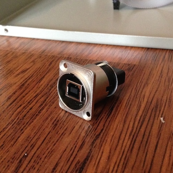
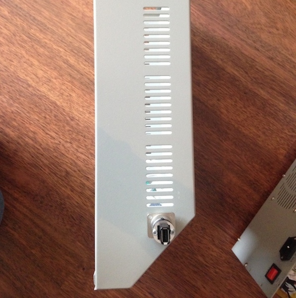
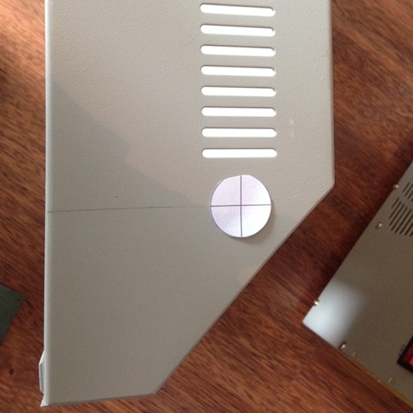
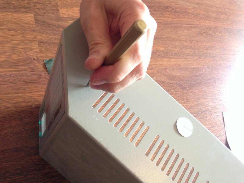
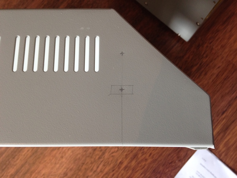
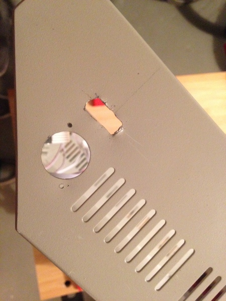
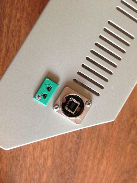
The following gallery shows the installation process:
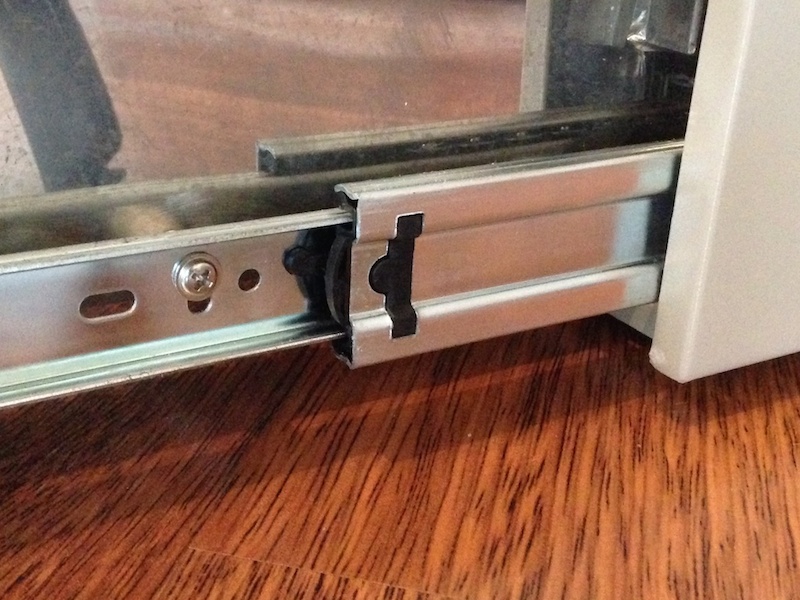
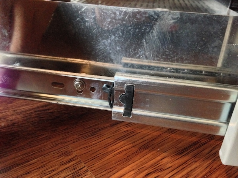
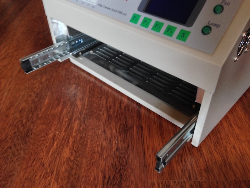
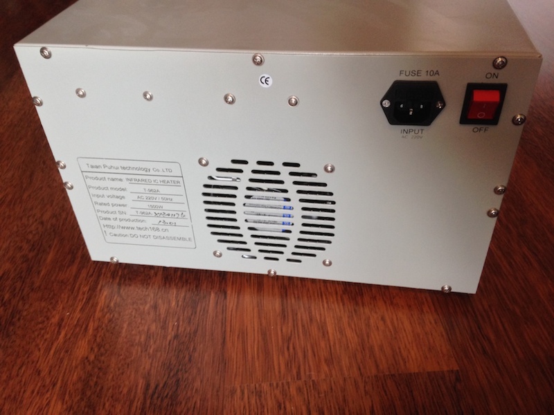
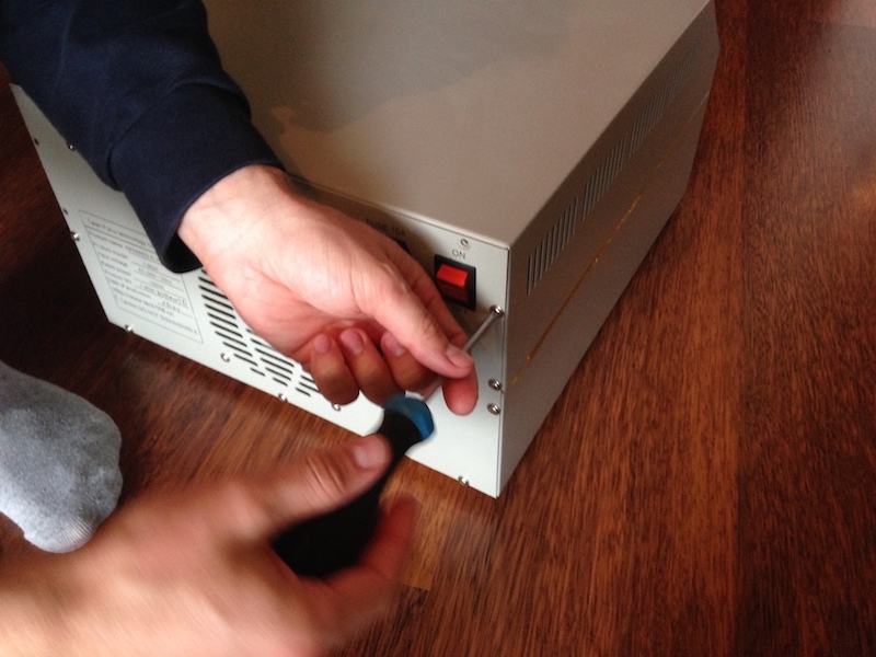
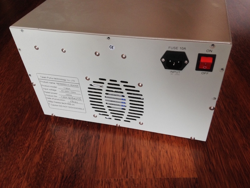
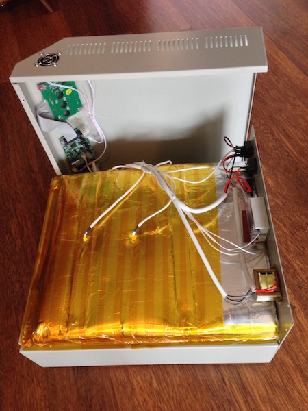
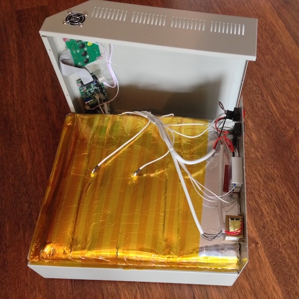
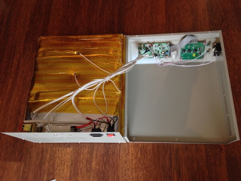
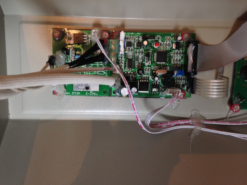
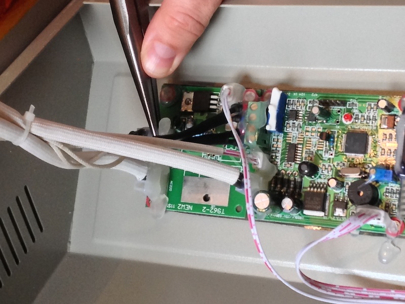
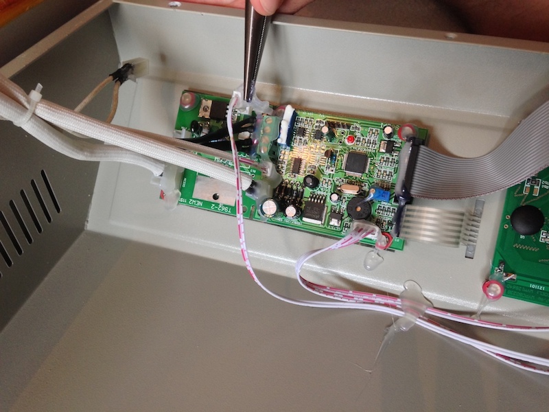
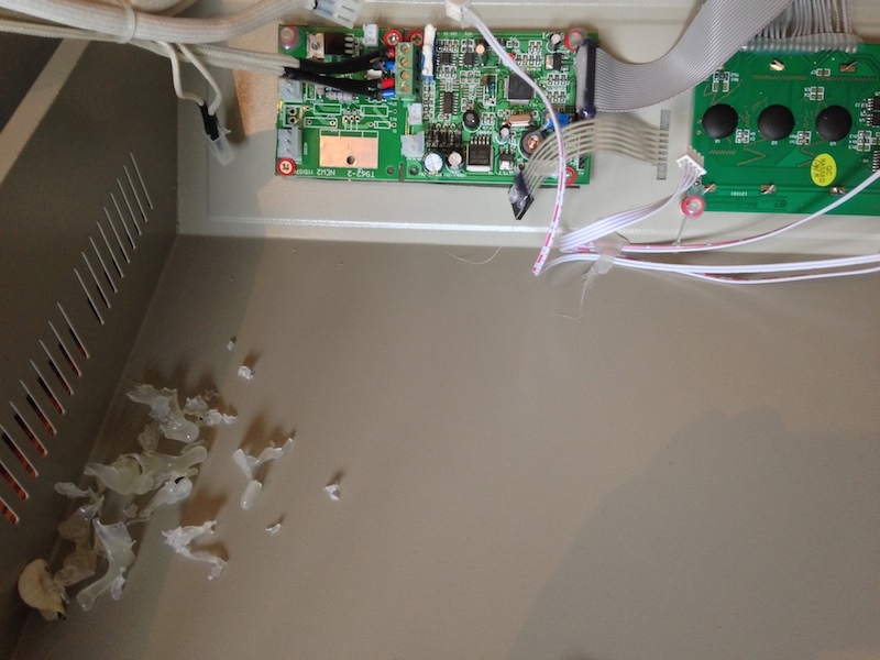
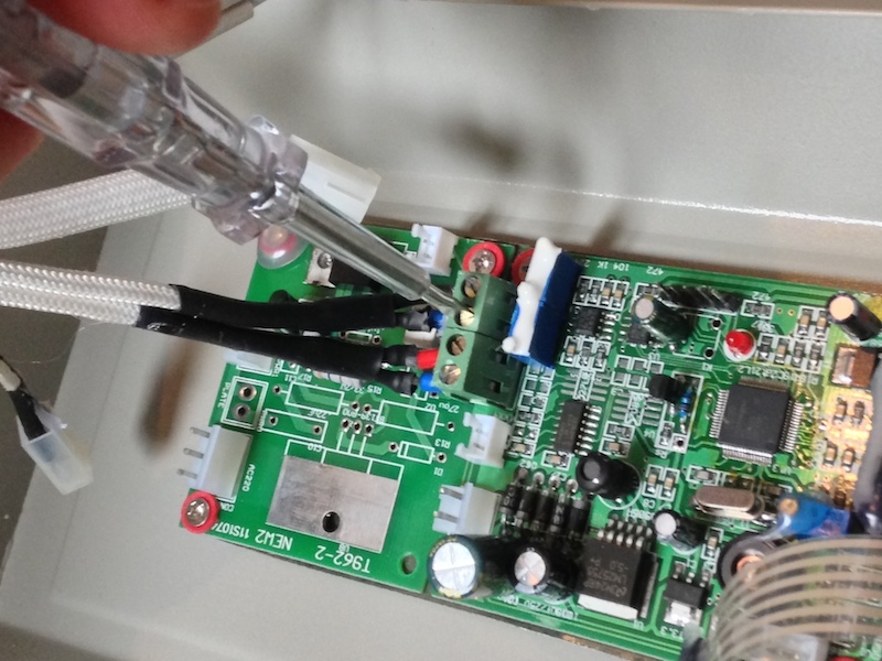
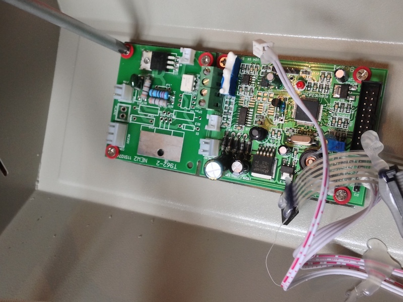
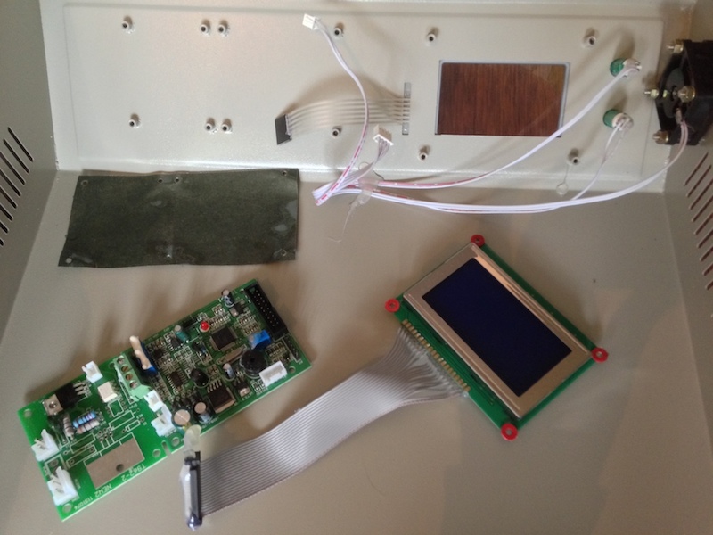
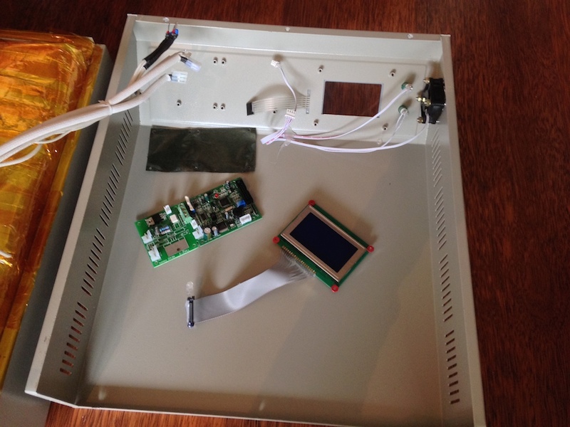
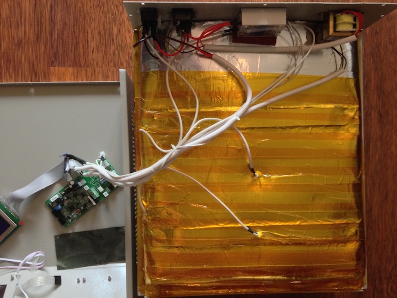
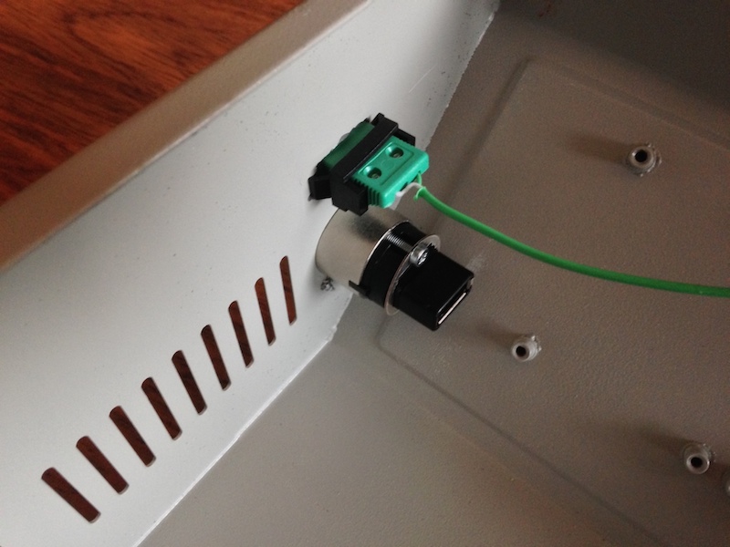
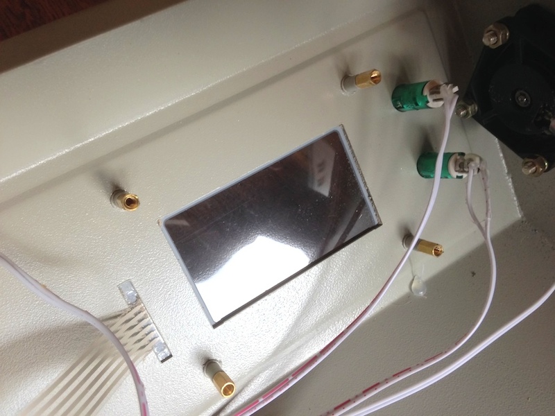
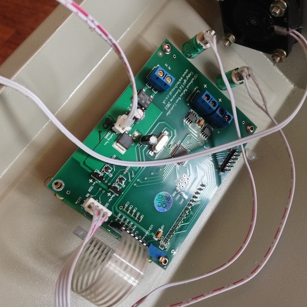
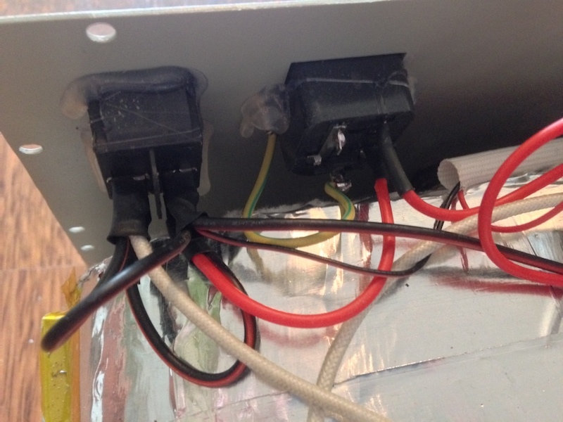
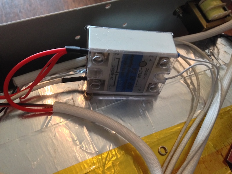
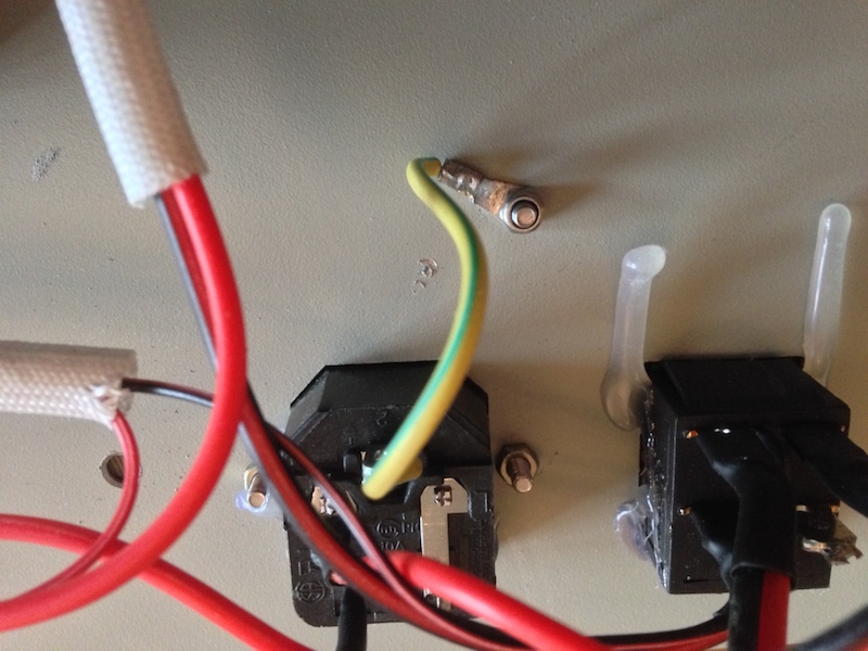
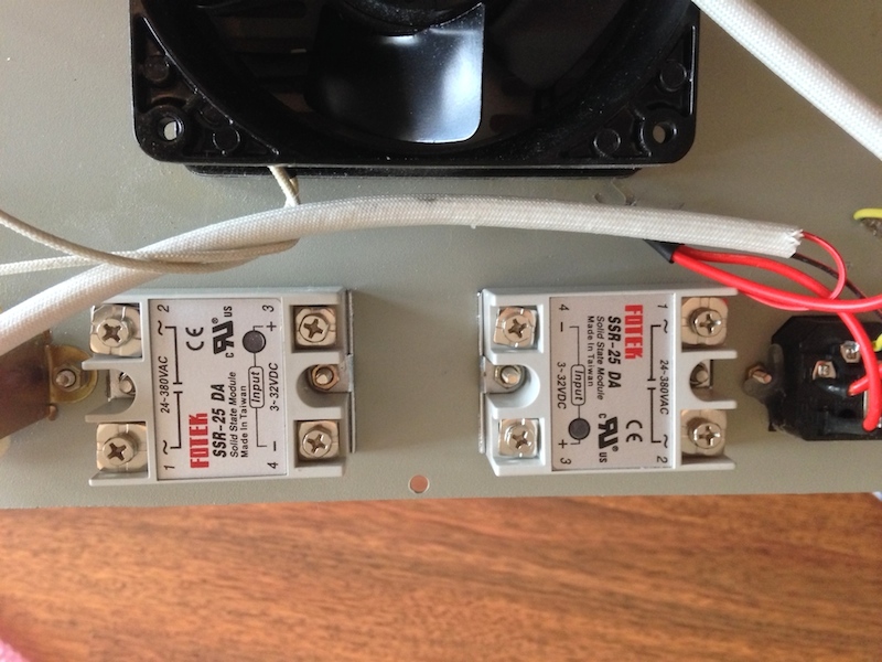
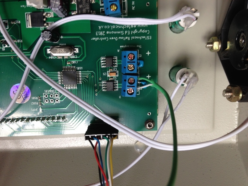
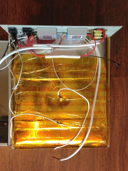
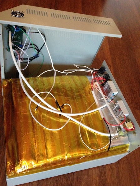
Overall, the installation of the upgrade took me around seven hours. I did not have critical problems that needed to be corrected, but I took my time when it came to the wiring to make sure that everything is connected correctly and that anything would destroy any component because of short circuits.
The GUI of the upgraded oven
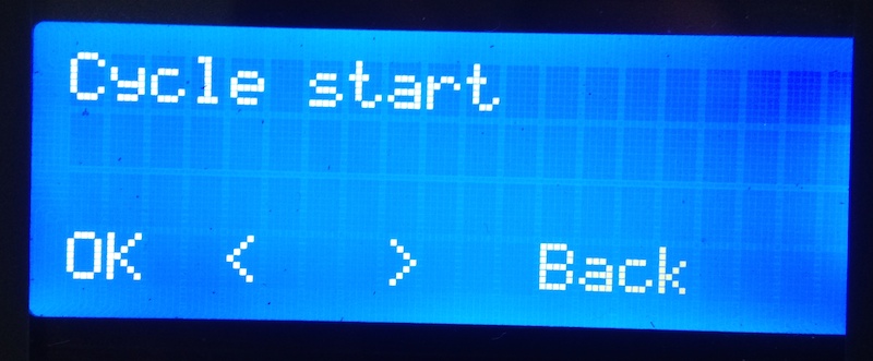
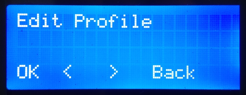
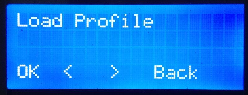
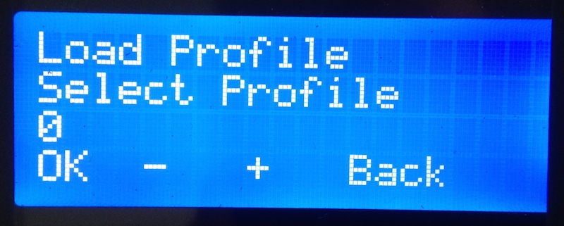
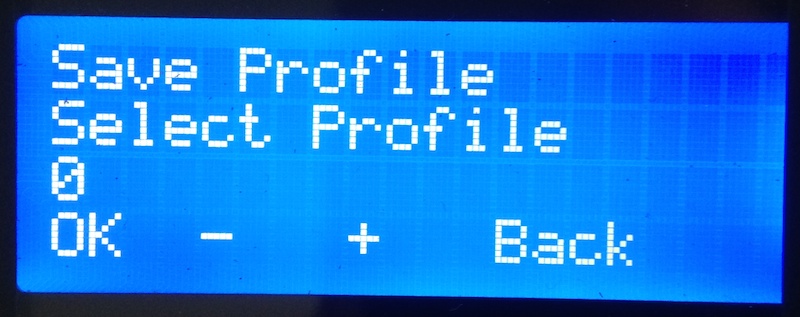
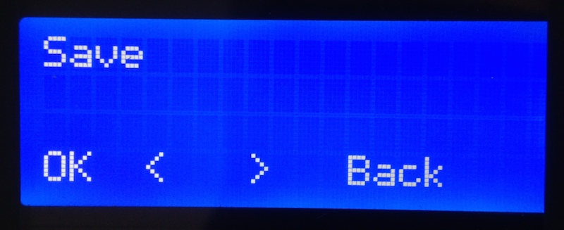
The ESTechnical control board comes with a complete replacement for the original user-interface. It controls the oven with a proportional-integral-derivative control (PID control) algorithm. While the original menu did not feel very responsive in certain situations the ESTechnical UI feels very solid and accurate. The menu is organized in the following way:
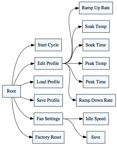
The following gallery shows images of the menu in reality:
Recommended Settings and Reading Status Information via PC
For lead-free soldering ESTechnical recommends these profile settings for a starting point:
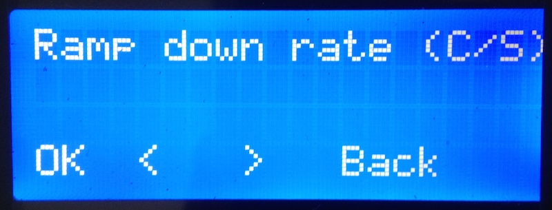
- Ramp up rate: 0.8°C/S
- Soak temperature: 130°C
- Soak duration: 30S
- Peak temperature: 220°C
- Peak duration: 10S
- Ramp down rate 3.0°C/S
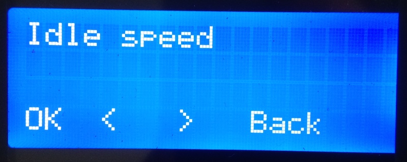
- Fan idle speed: 30-40
After the upgrade, the oven offers a serial COM port via the USB connector that can be used to read out status information of the oven, ESTechnical offers a Processing program “reflowViewer” that can be used to visualize and store these status information. I had to install Processing first, before I was able to run reflowViewer. To make that work you need to adjust the device name of the virtual COM port that is created when you connect the oven with your computer. In my case it is “/dev/tty.usbserial-A703OKHM”. The following image shows the GUI of reflowViewer:
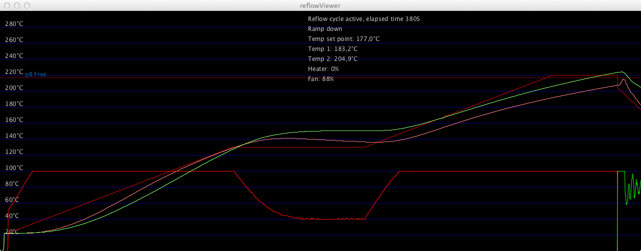
I was told by ESTechnical that soon they will be launching a new software for use with the oven and the controller that offers more functionality than reflowViewer.
Effects of Different Fan Speeds
A major difference between the upgraded version of the oven and the original oven is that the fan can be set to run at a fixed idle speed during the preheat, soak, and reflow phases. The intention for this is to have a more even temperature distribution within the oven and, therefore, more evenly heated PCBs. I run a series of cycles with different fan speeds and logged the oven data via the USB serial communication port and “reflowViewer”. You can see the measurement results in the following gallery:
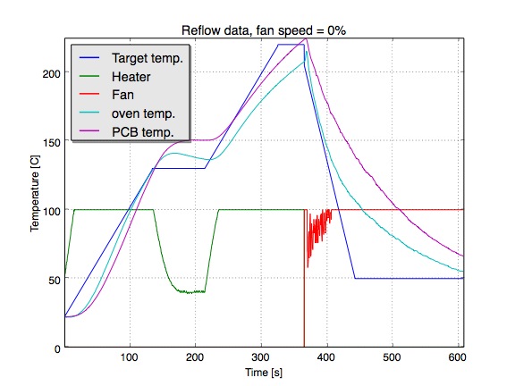
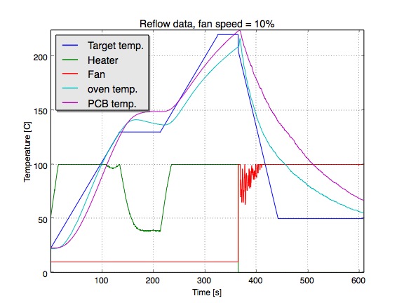
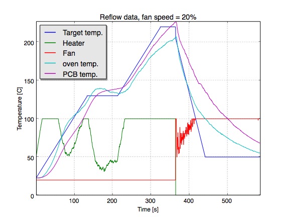
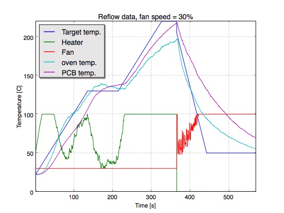
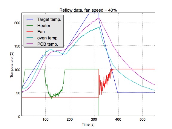
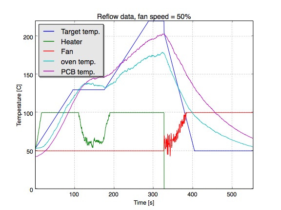
Comparing the observed PCB temperatures with the target temperature profile in each figure, it seems that an idle speed for the fan of 30% is a pretty good choice: With this setting the temperature does not significant exceed the peak temperature and is stays pretty close to the target temperature profile though out the whole soldering process.
The Upgrade kit comes with instructions and tuning tips for optimizing the parameters of the soldering profile.
Conclusions
The installation of the upgrade components took more work than I expected at the beginning. However, I am very satisfied with the results: The upgrade allows to have much better control about the soldering process. Also the parametrization of the soldering profiles is much easier and intuitive in comparison to the original oven controller UI. Having the possibility to measure the oven as well as the PCB temperature is a great enhancement. The additional air movement inside the oven due to the upgraded fan control is another huge enhancement on comparison to the original oven.
Do you have any questions or comments? Feel free to post these here!


Greetings, I have a question.
I have this oven, in its original state, and I am having a lot of trouble reflowing Lead-free. Right now, as it is, it only uses around… 10% maybe of the whole tray area, the rest doesnt manage to melt the soldering paste. I would like to know if this is a problem unique to my Heater or its a common issue that could be resolved by this upgrade.
I know its a really old post, but i still hope for an answer.
cheers
Hi, we’ve now launched our new documentation, if you are interested in the ESTechnical Reflow Controller upgrades or working on T962/T962A be sure to take a look at http://www.estechnical.co.uk/docs/doku.php
Hi, i also buy one of those reflow oven. Thank you guys for sharing those informations.
Well i also try to cook some pcb and lead free job is not ok with the standard oven. I try the profile 3. My board was quite big (300*177mm, it was a test board), and in many place the solder does’nt melt. So i decide to measure temperature with a K sensor and my multimeter. I perform 2 tests: first time the sensor was 2 centimeter behind the glass (dawner), at 2mm max above the PCB. Second test i put the sensor at the middle of the board (2mm max above the pcb). Test 1 the temperature offset measured is around 20°C under the lower temperature displayed on screeen during wave 3 process. The max temp during reflow was 224°C. Test 2 the temperature offset is 10°C under the lower temperature displayed on screen and max temp was 243°C.
My solder paste reflow temperature was 230°C to 250°C but this was’nt enough. On the edge of PCB the temperature is too low for this solder paste. I’ll try a leaded paste later.
About enhancement, what do you think about hold down thermal sensor?
I saw 3 trimmers on the main PCB, does someone try something?
About ESTechnical does it use PWM on heater?
Looking at the J-STD-020 specification for reflow ovens, it suggests that IR heaters should only heat air and not the components themselves. Unfortunately, the IR elements in this oven are directly above the boards. IR absorption is greater for darker components, so it leads to uneven heating. Another problem area for this oven is that all the heat comes from the top, so you’ll find larger components (microcontrollers, GPU etc.) are shading areas of the PCB from heat.
That said, the ESTechnical controller looks like a worthy upgrade and you have done a tremendous job documenting the process.
? That’s a spec for package moisture sensitivity testing. The profile there isn’t going to come from a hobby batch style reflow oven.
Looking at the graphs the heater is too small the thermal mass of the oven too large and the fan is exhaust not convection. That said the mod should be a little more likely to produce slightly more consistent results.
Frank I’d be careful stuffing it full of boards I’d bet the profile isn’t consistent around the chamber.
This website has more information on the oven that I have found anywhere else. Thanks.
Have you made any boards since installing the modifications?
How unreliable was the oven before you added the controller?
Was it useless or just every few boards needed rework?
Have you ever tried soldering through hole components with the oven?
Do you think the oven would be practical to use on a small run of 10 or 20 boards?
Glad that you find the article helpful!
I have made several boards (maybe around 50) since installing the modifications and the quality was very consistent.
Before adding the ESTechnical controller I used the oven also quite a lot to make boards. I cannot say that the oven was very unreliable in it’s original state, but by installing the new controller I got the impression that the whole soldering process is much more transparent and controllable. Especially the possibility to track the temperature directly on the PCBs in the oven is a huge improvement in my opinion.
I have not tried to solder through hole components with the oven yet.
The oven is definitely practical for small runs of 10 or 20 boards.