Getting Started with the RetroPie GPIO Adapter

Jul
This is a guide that describes how to get started with the RetroPie GPIO Adapter. It is organized as a step-by-step guide: Starting with the sole components and the PCB the hardware assembly is described in the first part. The second part then guides you though the software topics by describing how to test the button and how to enable SNESDev for polling the controllers.
Hardware: Assembly of the RetroPie GPIO Adapter
The assembly of the RetroPie GPIO Adapter can be done as following:
[tabs type=”horizontal”] [tabs_head] [tab_title]Revision 2.X[/tab_title] [tab_title]Revision 1.5 to 1.7[/tab_title] [tab_title]Revisions 1.0 to 1.4[/tab_title] [/tabs_head] [/tabs]Hardware: Connecting the ribbon cable with the adapter
The RetroPie GPIO Adapter was constructed such that it is able to poll up to two game pads that make use of a shift-register for serializing the status of each component of the game pads. The SNES and NES controllers work in this way. In the following it is described how to connect two SNES sockets to the ten-wire ribbon cable.
The ribbon cable is used to connect the SNES sockets with the 2×5 pin header of the RetroPie GPIO Adapter.
One end of the ribbon cable gets a crimp connector. To make the description easier in the following take care for the salient on the crimp connector so that the pin out looks like this:

With the assumption that the salient faces upward, the pin out of the 2×5 header on the RetroPie GPIO Adapters revision 1.X look as shown in this figure:
The RetroPie GPIO Adapter revision 2.X get the ribbon cable attached in this way:
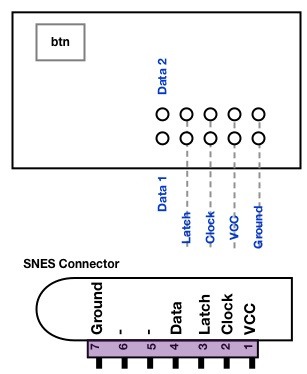
Hardware: Connecting SNES sockets with the ribbon cable
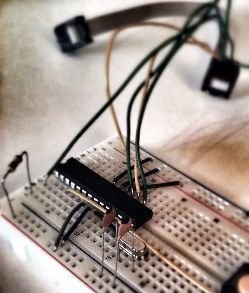
Now, you need to solder the ten wires of the ribbon cable to the pins of the two SNES sockets. The pictures above show the pin out of every single wire of the cable as well as the pin out of a SNES socket. You need to rip up the ribbon cable, dismantle the insulation and solder each wire to the according pin of the SNES sockets. The result might look similar to what is shown in this picture: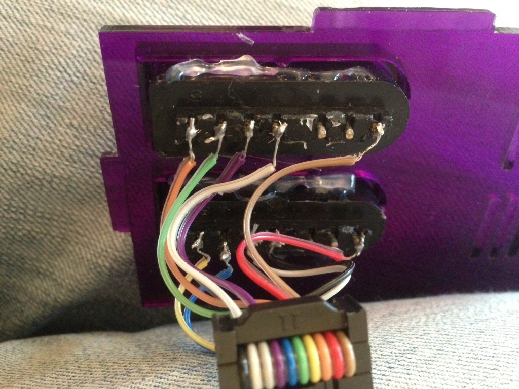
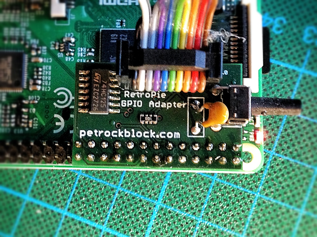
Hardware: connecting the RetroPie GPIO Adapter with the Raspberry Pi
During the design of the board I was not aware of the “safe mode” of the Raspberry Pi: Adding a jumper between pins 5 and 6 of P1 results in /boot/config.txt being ignored (except for avoid_safe_mode) and a default cmdline.txt is applied, followed by loading kernel_emergency.img. As stated in the official forum
if you connect external hardware to that pin, the worst that will happen is it falsely triggers safe mode.
To avoid this safe mode when the adapter is attached a setting has to be made in /boot/config.txt. This could be done, for example, by opening the config.txt with
sudo nano /boot/config.txt
adding
avoid_safe_mode=1
and saving the changes with “Ctrl-X”, which has to be confirmed with “Y”.
The adapter must be put on the GPIO pins of the RPi such that the 2×5 pin header faces inwards the PCB of the RPi.
Software: A tool for testing the button
In order to check the correct assembly of the adapter, you can test the button first. A simple command line tool is contained in the SNESDev repository. You can install SNESDev either by using the RetroPie Setup Script or by following the instructions on the welcome site of the SNESDev repository. The command line tool testButton is contained in the subfolder supplementary/testButton/. While the tool is running it continuously prints the status of the button to the console. You can exit the program with “Ctrl-C”.
SNESDev, which is described in the next section, counts the numbers of button presses and reacts differently to these: If you press the button 3 times, the press of the ESC key is simulated. If you press the button 5 times, the shutdown command is executed.
Software: SNESDev for polling the game pads and the button
SNESDev is a user-space device driver especially written for the RetroPie GPIO Adapter. It implements two (S)NES game controllers and a virtual keyboard for up to two (S)NES controllers and a button that are connected to the GPIO pins of the Raspberry Pi via the RetroPie GPIO Adapter.
SNESDev can be enabled from within the RetroPie Setup Script. You find the option for that in the when you select “Setup” in the main menu of the script. The RetroPie Setup Script can also be used to install a kernel-space driver for polling various game pads, which is also known as “gamecon driver”. Do not enable the gamecon driver and SNESDev at the same time, because both access the GPIO pins and they do interfere with each other. It is recommended to use SNESDev as driver for the RetroPie GPIO Adapter.
You can either install SNESDev manually: a complete installation guide can be found here in the repository of SNESDev. Alternatively, you can use the RetroPie Setup Script for installing and configuring SNESDev. IMPORTANT: As described in the README of SNESDev, you might need to configure the correct version of the RetroPie GPIO Adapter. The default version is 2.X. If you find a revision number 1.X on your RetroPie GPIO Adapter you need to set the configiration parameter “adapter_version” to “1x”.
The correct connection with the game pads can be tested from command line with the tool jstest, which is installed with the command sudo apt-get install joystick.
If you want to test your first game pad, you run jstest /dev/input/js0 and get an output similar to this:
Axes: 0: 0 1: 0: Buttons: 0:off 1:off 2:off 3:off 4:off 5:off 6:off 7:off
To test your second game pad you can use the command jstest /dev/input/js1. If you are using Emulation Station and want it to show the input configuration screen again, you need to delete the file /home/pi/.emulationstation/es_input.cfg to have Emulation Station show the configuration screen again.
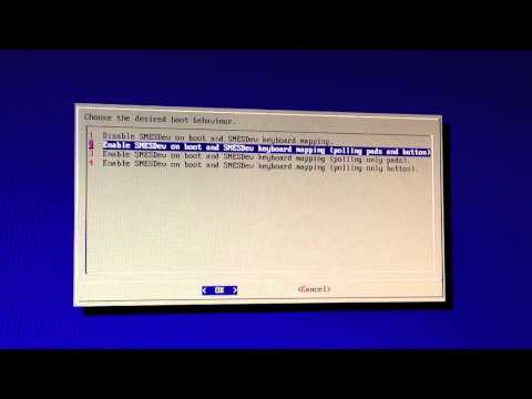
Video Guide
Here is a short video that should also support you with the installation:
Conclusions
This concludes the tutorial for getting started with the RetroPie Adapter. If you feel that any information is missing in this guide feel free to give comments!


I’m thinking in build a retroPi with a NES and want to use the original controllers. Is there any specific schema or tutorial for NES controlers?I want to use both originals controllers and sockets but only find info for SNES. From format SD, and solder retroPie adapter, to first game; how many time is required? Any shop for a kit?
Very very thanks you for tutorials.
I surprised how people made run hungry made linuxes (currently modren linux based flavor are resource eaters ) are capable to run “softly” in those minimal devices!but i nosee a linux runni in a “Pi” and runs very slow!
Does this adapter have any problems with the Raspberry PI2 B+? The adapter worked as expected when i used it on my RPI-B. But now i can’t get any response from the controllers or the button. I have checked that SNESdev is running and i have added avoid_safe_mode=1 in /boot/config.txt. I also checked my solderings and how i wired the controller 2 times before posting. But jstest /dev/input/js0 or js1 does not take any inputs. It shows that 2 controllers are connected when you launch emulationstation the first time.
Any idea what it could be?
I have tested it and I can say that the GPIO Adapter works with the PI2 B+. It might be that you need to recompile and re-install SNESDev. A description for that is given, e.g., at https://github.com/petrockblog/SNESDev-RPi#installation.
Hope that helps!?
Hello guys, I need you expertise in this.
The past weekend I’ve wired my NES controller adapter directly to the GPIO of my RasbPi ModelB Rev2.0 and installed the RetroPie with the latest image.
When I run the EmulationStation, it detects the gamepad but none of the buttons work. This is what I’ve done:
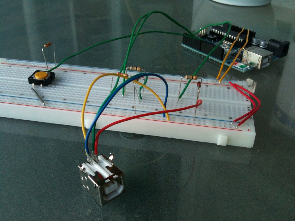
First I’ve wired the controller to the GPIO like this:
GPIO PIN1 – 3.3v
GPIO PIN6 – GND
GPIO PIN16 – Latch
GPIO PIN18 – Clock
GPIO PIN22 – Data
After installing the latest image of RetroPie, I’ve expanded the filesystem in the RasbPi and overclocked it to 950Mhz.
After this config, I’ve opened the RetroPie setup and updated the binaries and the setup script. After that, enabled the SNESDev with buttons and polling and rebooted the system.
Configured the SNESDev.cfg to one gamepad and changed “snes” to “nes”. Rebooted again.
When EmulatioStaiton opens, it detects 1 gamepad but none of the buttons work. And i’ve been stuck here until today. Already read all of the guides here, other sites on the web, everything!
Does you guys have an idea what can I do next?
Thanks in advance
Sorry my english. I’m from Portugal.
— Ivo
:( I’m having issues with my Snes controller set up, emulationstation says 2 controllers detected so I’m assuming the adaptor is working correctly, the button on the adaptor also works and prints “R” in the Jstest, but the controller doesn’t seem to work in the jstest or in emulation station. i’ve double triple checked the connections and everything appears to be fine…. any advise?
Just some random thoughts:
– are there any shorts?
– Are the SNES connectors attached like shown in the image “Ribbon cable pinout on the RetroPie GPIO Adapter revision 2.X” above?
why is this adaptor necessary at all, surely the controllers are serial so could in theory be wired directly to the Pi GPIO’s
To read the status of a SNES controller you can connect controllers directly to the GPIOs of the RPi. The adapter provides protection and assembly comfort: The adapter provides additional circuitry protection against shorts and transients. It also makes the connection to SNES connectors easier by providing a dedicated 2×5 pin header for that. Not more, and not less.
thanks :) for the reply
So I’m partially retarded I think I was so excited that I still remembered how to solder that I didn’t follow directions very well and soldered the everything on the same side of the board. ( The 2×13 pin connector is on the wrong side any advice how to correct this issue? I am trying to use a copper braid to suck the solder out and am not having alot of luck any advise would be awesome.
See https://www.petrockblock.com/forums/topic/gpio-adapter/.
Hello. I bought a GPIO Adapter and have soldered it up, connected it up just fine and have verified that my joypads are working using JSTEST. However, when I run emulationstation and try and configure the controls, when it asks me to configure the controls for player 1, after a couple of seconds it automatically progresses through to player 3. It’s as though it’s receiving inputs from devices even though I haven’t connected anything. Any suggestions as to what this might be?
The discussion can be found in the forum at https://www.petrockblock.com/forums/topic/random-activity-on-js3/.
Hi mate. No luck with trying to get the SNES pads working. I’ve got as far as installing retorpi, installing SNESDev (starting from boot with keyboards and pads polling) but when I get to the white screen where it says press button for player 1, nothing is picked up. Can you suggest any troubleshooting tips? Also just to double check, does the 2×5 pin face into the pi board or away from it (ive tried both ways to no avaial but I wanted to be sure which one was right!!!) Thanks.
The 2×5 pin header has to point into the pi board.
Did you try and test the button of the adapter (described above in the section “Software: A tool for testing the button”).
Double check, if all pin connection to the SNES connectors are soldered correctly.
Did you follow the steps described in section “Software: SNESDev for polling the game pads”? Does the jstest command give you any further hints?
I’ll give it all a try. Thanks for the reply.
Still no further with it mate, doing my nut in now. Can’t get the jtest to work, just says no such location or something along those lines (currently doing a full reload….) Could you check my board to see if the ribbon is right? Header facing down and black on the far side. Desperate to get this working…
The orientation of the ribbon cable matches that of the description in this article.
There was a typo in the js command in the article that I just fixed. It should be jstest /dev/input/js0
Maybe a video would be helpful here that would show the steps for installing and configuring SNESDev. Which information/content would be helpful for you? I could try and generate such a video within the next few days …
Alternatively, you could also post your question in the forum at https://www.petrockblock.com/forums/forum/retropie-project-forum/emulators/.
Thanks for offering to make a video mate. If i’m honest, a video from start to finish would really help. I’ll try the jstest without the s on the end of input tonight. One other thing, I’m using a 3rd party replica pad as opposed to an official nintendo SNES pad – do you think that would affect if or have you used/heard of people using the replica pads and them working.
Once again, thanks for your help.
A replica should work as well – in the end it has to use the same protocol as the original pads for polling the button states.
I cannot make any promises, but there is a slight chance that I can make that video within the upcoming weekend.
No worries. I’m very grateful for all your help. Anything you can make and whenever you can make it will be greatly appreciated. I’ve got a bit of spare time this weekend so going to give it another go, looking at everyone elses comments and the guides you’ve made – maybe it will work!!
Hi mate, quick update. I got the jtest working. It said off off for all but every now and then the axis ones would flash a number up and off for a split second.
This might indicate a broken solder connection on the connectors site.
How would I test/fix that?
I mean the connection between the ribbon cable and the SNES connectors. Just a guess, though.
I think they’re all fine mate. Checked them :-S
I have just uploaded a video. Maybe this clarifies things: https://www.petrockblock.com/2013/07/09/getting-started-with-the-retropie-gpio-adapter/#videoguide
what is the IC74HC125? And my PCB I received is slightly different than the one shown
There has been a minor change in the PCB layout lately. This change added two additional pull-up resistors to enhance the SNES connector interface in case of unconnected gamepads. All resistors are combined within a single SMD component, a resistor network. The adapters with this change have the revision number 1.5 and I would guess that you also have such an adapter. If you are interested, the updated schematics can be found at https://www.petrockblock.com/download/retropie-gpio-adapter-schematics-rev-1-5/.
Also the assembly guide for the most recent adapter was just updated here.
I hope that helps!?
Maybe you could add hookup diagrams for NES controllers and not just SNES?
Good idea! I will add the diagram in the next days.
Awesome! Thanks! Just wanted to make sure NES controllers would work :) And now I think I’ll buy one of the adapters :)
Until the diagram is added, you can find a description and a diagram for hooking up NES controllers at http://www.igorkromin.net/?x=entry:entry130215-145850.
Is there a diagram for this yet?
Got this last wick and soldering it wasn’t bad at all! I was having issues getting SNESDev to autostart at boot though with the part of the guide on Github. So instead I made a executable script and added it the root crontab “@reboot bash /home/pi/scripts/snesdev.sh” and all the script says is ‘#!/bin/bash /usr/local/bin/SNESDev’, Works great!
could you wire the SNES controller directly into the GPIO adapter instead of having an extension socket?
Yes – you could wire up to two SNES controllers directly into the GPIO adapter.
how would I go about that? I’ve striped the covering for the five little wires which are white, blue, yellow, red, beige. from left trigger to right in that order.
The image above (https://www.petrockblock.com/wp-content/uploads/2013/05/ImageUploadedByTapatalk1368731520.973453.jpg) shows the connection between the pins and the GPIO Adapter. That should give sou the information you asked for, I hope.
Does anyone know where you can buy the SNES sockets in the UK/Europe? I can only find US suppliers and it costs more in postage than the sockets cost!
So far, the easiest way I found is to buy one or two extension cables for SNES controllers. You can get these at eBay, Amazon, and many other electronic distributors.
Is the button a standard momentary switch? Could you wire any switch to the same terminals? I ask because I am putting a rpi in an old broken NES, and I want to use the reset button on the nes as the “esc” key to exit games. Would I be able to wire it to the adapter? Because a switch on the rpi itself is not very useful for my purposes. Also, can it be changed so that it doesn’t need to be 3 presses? I would rather it responded to a single press.
Both is possible! Please have a look at https://www.petrockblock.com/forums/topic/the-momentary-on-push-button-gpio-adapter/
You would have to modify SNESDev to make the ESC key be simulated with one press. But that would only by minor modifications.
wish my brother would have read the description of the item as i can solder to save my self lol hopefully i dont stuff it up 2 bad